
Telephone Ring Indicator Circuit

The integration of a neon lamp as a ring indicator in a telephone line circuit serves as an effective visual alert for incoming calls. This application is particularly beneficial in environments where auditory signals may be overlooked or inaudible, such as in noisy workplaces or for individuals with hearing impairments.
To implement this circuit, the neon lamp should be connected in parallel with the phone line. A typical configuration would involve placing a resistor in series with the neon lamp to limit the current flowing through it, ensuring that the lamp operates within its specified voltage and current ratings. The resistor value can be calculated using Ohm's Law, taking into account the operating voltage of the phone line, which is usually around 48 volts DC when idle and may spike higher during ringing.
When the phone rings, an AC voltage is applied across the line. This voltage causes the neon lamp to ionize and emit light, providing a clear visual indication of an incoming call. The choice of neon lamp should consider the brightness and visibility required for the specific application environment.
It is essential to ensure that the components used are rated for the voltages encountered in the telephone line to prevent damage or failure. Additionally, the circuit should be housed in a protective casing to prevent accidental contact with live parts. Proper insulation and safety measures must be observed to ensure user safety and compliance with electrical standards.
This simple yet effective modification enhances the functionality of traditional phone systems, providing an alternative alert mechanism that complements auditory ring signals. A neon lamp can easily be added to the phone line to act as a ring indicator. It`s perfect for times when you can`t hear the phone.
Related Circuits
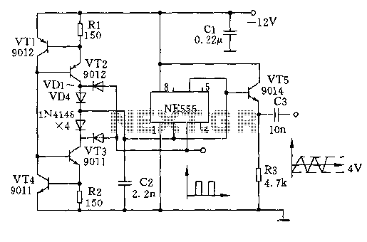
The circuit depicted involves transistors VT1, VT2, and resistor R1, which form a constant current source for charging capacitor C2 in a linear manner. Transistors VT3, VT4, and resistor R2 create a constant current source for discharging capacitor C2,...

This is a UHF band TV antenna preamplifier circuit with a gain of 15 dB, built using a BF180 UHF transistor. The circuit is straightforward in design. The operational principle consists of two stages. The first stage features a...
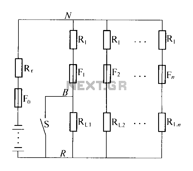
The circuit diagram illustrates a high-impedance distribution system characterized by low resistivity distribution. A notable feature is the series resistance of the shunt load current limiting resistor R1, typically valued at five to ten times the internal resistance of...

Retired Physics Professor Steven E. Jones is working on a simple overunity circuit that he has observed achieving up to 20 times overunity. This circuit is a variation of the Joule Thief or a blocking oscillator. His design incorporates...
The 7th overtone of 18 MHz (17m) is 144 MHz (2m) directly within the CW region. Icarus is a high-altitude balloon (HAB) project funded by advertising revenue, which has successfully launched numerous balloons that captured impressive photographs. Robert Harrison...
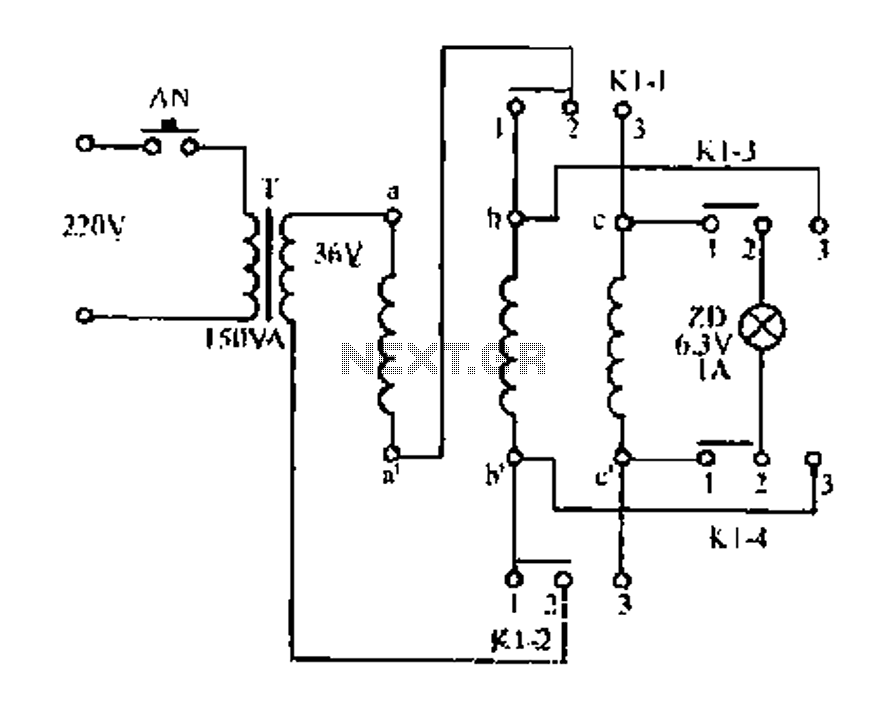
Figure aa, bb, and ce represent three-phase windings. A double throw switch Kl-1 to Kl-4 is positioned on the left side, connecting phases 1 and 2. At this point, aa and bb are in series with the secondary of...