
15dB UHF Antenna Preamp Circuit

The UHF band TV antenna preamplifier circuit is designed to enhance the signal quality received by the antenna, making it particularly useful in areas with weak signal reception. The BF180 transistor serves as the active device in this circuit, providing the necessary amplification to improve the overall performance of the antenna system.
The first stage, which consists of the band-pass filter, is crucial for selecting the desired frequency range while rejecting unwanted signals. The components involved—C1, CV1, L1, L4, C7, and C3—work together to shape the frequency response of the circuit. C1 and CV1 are capacitors that, along with the inductors L1 and L4, form a resonant circuit that allows only the UHF frequencies to pass while attenuating others.
The second stage employs a common-base voltage amplifier configuration. This configuration is characterized by its low input impedance, which is beneficial for matching the output of the band-pass filter with the input of the amplifier. This matching is essential for maximizing power transfer and minimizing signal loss.
The inductors L1 through L4 should be constructed as air core coils to achieve a high Q-factor, which is indicative of the coil's quality and efficiency. A high Q-factor minimizes energy losses and enhances the selectivity of the filter. The construction of air core coils involves winding insulated copper wire around a non-conductive form, ensuring that the coils are spaced appropriately to avoid coupling and interference.
Once the circuit is assembled, it is recommended to place it inside a metallic enclosure. This enclosure serves multiple purposes: it protects the circuit from physical damage, shields it from electromagnetic interference, and helps to ground the circuit effectively. Proper grounding to the enclosure is critical as it helps to eliminate noise that could degrade the performance of the preamplifier, ensuring clearer signal reception.
Overall, this UHF band TV antenna preamplifier circuit represents a practical solution for enhancing signal strength and quality in UHF television reception applications.This is an UHF band TV antenna preamp circuit with 15dB gain and build by a transistor. It is formed based on BF180 UHF Transistor. This circuit is a simple circuit. This is a figure of the circuit. The principle operation of the circuit is two stages. The first stage is an band pass filter constructed by the C1, CV1, L1, L4, C7 and C3, the second stage is a base-common voltage amplifier with low input impedance to match. Build the L1 ~ L4 as air core coil to obtain high Q-Factor. You can find out about air core coil construction and calculation here. After assembling, pack it into a proper metallic box and connect the ground of the circuit to the box to reduce noise effect. 🔗 External reference
Related Circuits
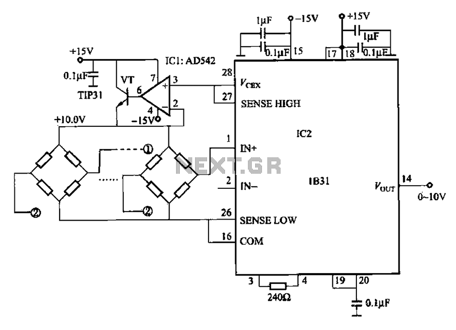
The 1832 low drift input has a temperature coefficient of 0.07 µV/°C (RTI, G 500) and exhibits excellent linearity with a maximum deviation of 0.005%. It can drive resistive loads greater than 120 ohms in a bridge excitation circuit,...
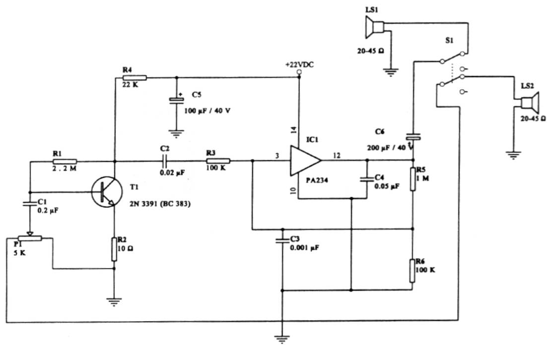
This intercom circuit is versatile and can be utilized in various applications. It operates at 22V, although it may function at a lower voltage (experimental testing is suggested). The circuit utilizes a loudspeaker with an impedance of 20-45 Ohms...
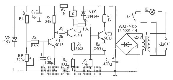
The circuit operates as a light-activated switch that controls white moving lights. It features high sensitivity, stable performance, and good anti-interference characteristics. A photosensitive resistor (RI) is employed to detect ambient light levels. During the day, the resistor exhibits...
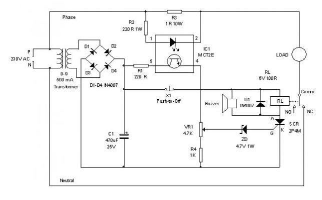
An electronic circuit breaker is designed to detect overload conditions and disconnect power when the load exceeds a predetermined threshold. This circuit is particularly suitable for safeguarding Uninterruptible Power Supply (UPS) devices, such as inverters. The electronic circuit breaker operates...
Two-Tone Siren Circuit Schematic Using One IC. This circuit is designed for children's entertainment and can be installed on bicycles, battery-powered cars, motorcycles, as well as models and various games and toys. It includes a switch (SW1) for operation. The...
A bandpass filter allows a specific range of frequencies to pass while rejecting frequencies that fall outside the upper and lower limits of the passband. The frequencies that are permitted to pass are referred to as the passband, which...