
Telephone ringer piezoelectric

The electronic bell circuit is designed to function autonomously, utilizing a piezo buzzer as the sound-producing element. The circuit architecture is simplified, relying on passive components such as resistors and capacitors, with specific emphasis on the values of C2, R2, and R3, which are critical for optimal performance. The omission of resistor R1 is a design choice that directly influences the sound output level, allowing for a louder ringing tone, which may be desirable in certain applications.
The piezo buzzer, a key component in this circuit, is versatile and can be sourced from various suppliers, leading to potential variations in specifications. The connection scheme for the buzzer is straightforward: the red lead is to be connected to the collector of the transistor Q1, while the black lead connects to the emitter. This configuration is essential for the proper functioning of the circuit, as it allows the transistor to control the piezo buzzer effectively.
In cases where the piezo buzzer includes a third lead, typically colored blue, this lead is connected to the base of transistor Q1. This additional connection can enhance the control over the buzzer's operation, providing more refined modulation of the sound output. The overall design of the electronic bell circuit is efficient and user-friendly, making it suitable for various applications where a simple, battery-free sound signaling device is required.The electronic bell needs no power supply. Most of the resistors are not critical, although C2, R2, and R3 work best at the values given. Leaving out Rl will make the unit ring louder. The piezo buzzer may vary from store to store. If it has two leads, connect the red lead to the collector and the black lead to the emitter of Ql If a third (blue) lead is present, connect it to the base of Ql.
Related Circuits
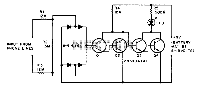
The LED flickers when the phone is ringing or being dialed. It glows steadily when the phone is off the hook. The described circuit involves an LED indicator that serves two primary functions based on the state of the phone....
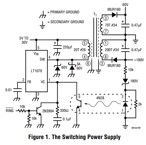
Here is a design that you can own, tailor to your specific needs, layout on your circuit board and put on your bill of materials. Finally, you will be in control of the black magic (and high voltages) of...
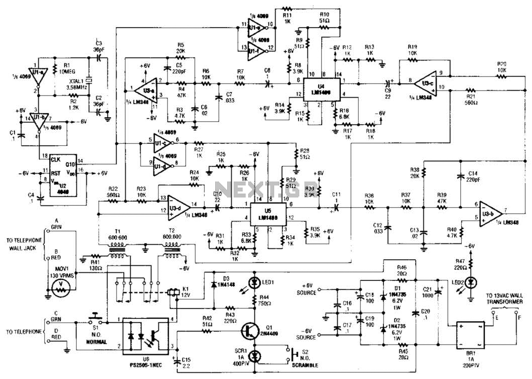
Two hybrids (T1 and T2) are utilized to facilitate a direct connection to a telephone line. This circuit employs a standard speech-inversion algorithm, which inverts the frequency of an audio signal around a central frequency. An LM1496 balanced modulator...
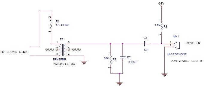
What type of microphone or mouthpiece can be used to connect to a POTS (Plain Old Telephone Service) telephone line to send DTMF (Dual-Tone Multi-Frequency) tones only, without transmitting voice? Is a standard microphone suitable, or must it be...
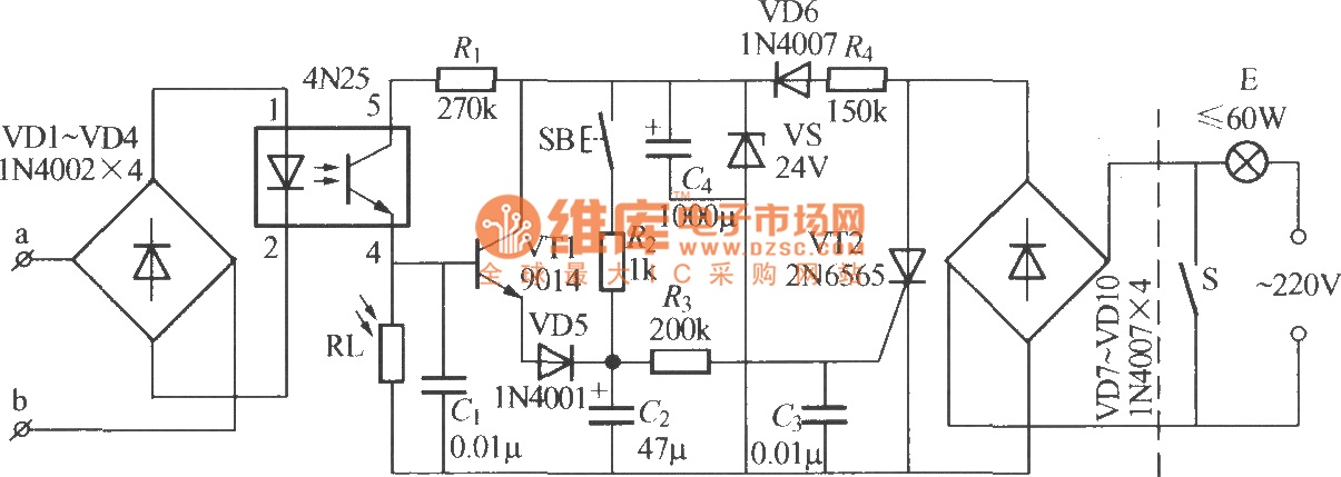
The diagram illustrates an automatic lighting control circuit activated by a telephone. At night, when the telephone rings or the user picks up the receiver, the light turns on. If the telephone stops ringing (when no one is listening)...
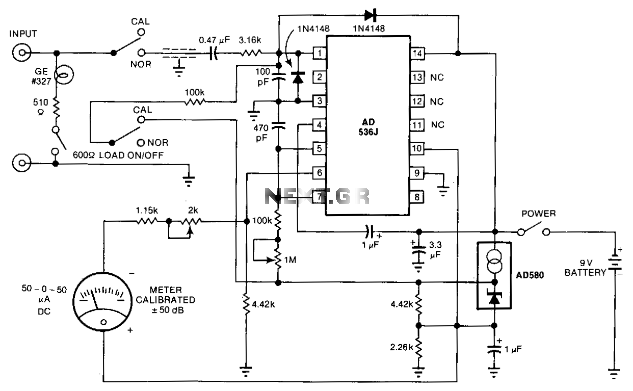
The telephone-line decibel meter and line-voltage sensor enables accurate monitoring and adjustment of telephone sound levels. The 600-ohm resistor appropriately terminates the line. The power consumption from the 9-volt battery is 2 mA, and the meter offers a ±30...