
Telephone control automatic lighting circuit 1

The automatic lighting control circuit operates based on the principles of telephone line signaling. The circuit is designed to interface with the telephone system, detecting the ringing signal or the off-hook condition. A relay or transistor can be utilized to control the lighting load, ensuring that the light is activated when the telephone signals activity.
When the telephone rings, the circuit is triggered by the AC ringing voltage, which energizes a relay. This relay closure connects the light to the power supply, illuminating the light fixture. The duration of illumination is controlled by a timing circuit, which can be implemented using a simple RC (resistor-capacitor) delay timer or a microcontroller that can be programmed to provide the desired timing functionality.
In the case where the telephone stops ringing or is placed back on-hook, the timing circuit initiates a countdown that allows the light to remain on for a predetermined period (10 to 40 seconds) before automatically turning off. This feature ensures that the light does not remain on indefinitely, conserving energy when it is not needed.
The manual light-triggering button provides an additional method for activating the light without relying on the telephone's signaling. When pressed, this button temporarily bypasses the timing circuit, allowing the light to stay on for approximately 40 seconds. This feature is particularly useful in situations where immediate illumination is required without waiting for the telephone to ring.
Overall, this circuit design combines automatic and manual control mechanisms to provide efficient lighting solutions, particularly in environments where telephone activity is frequent during nighttime hours. Proper component selection, including relays, resistors, capacitors, and possibly a microcontroller, is essential for the reliable operation of this circuit.The diagram shows telephone control automatic lighting circuit. At night, when telephone rings or master takes up telephone transmitter dialing, the light can lighten; when telephone ringer stopped (no one listen) or on-hook, it can delay 10~40s, then the light can die out itself. Moreover, this circuit also set a light triggering button. The ligh t can lighten about 40s only by pressing the button. 🔗 External reference
Related Circuits
The circuit is compatible with all 2323 chips, but it is optimized for the AT90LS2323, which operates at a voltage range of 2.7 to 6 volts. The microcontroller utilized in this design is the AT90S2323, which functions effectively within...
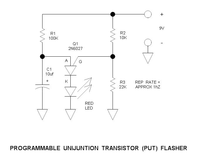
This is a simple circuit that illustrates the function of the programmable unijunction transistor. It can be quickly wired on a proto-board. The circuit utilizes a programmable unijunction transistor (PUT) to demonstrate its operation as an oscillator. The PUT, which...
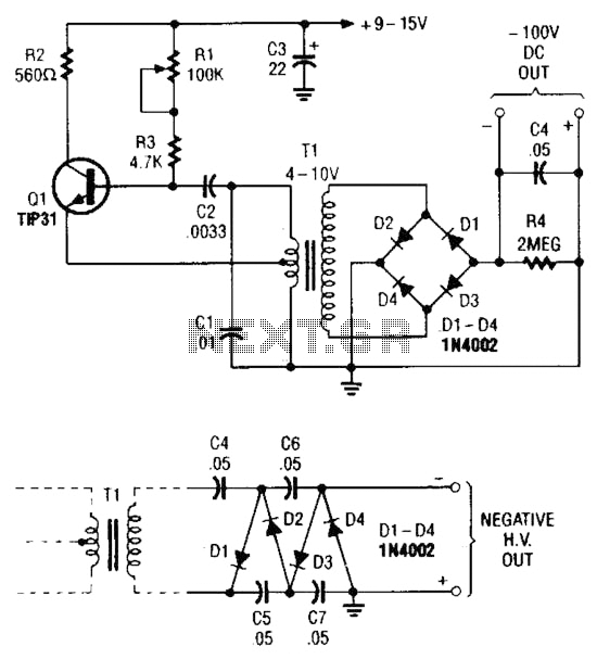
The combination of a Hartley oscillator and a step-up transformer can generate significant negative high voltage, particularly when the voltage output of the transformer is multiplied by the circuit. The Hartley oscillator is a type of LC oscillator that utilizes...
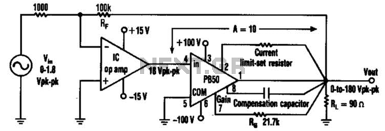
An Apex PB50 Booster Amplifier, along with an integrated circuit (IC) operational amplifier, can be utilized in a high-voltage operational amplifier configuration to convert a small analog signal into a 180-V peak-to-peak signal. Apex Microtechnology produces a variety of...
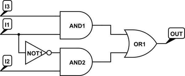
There are integrated circuits that contain AND, OR, and NOT gates. The inquiry revolves around the existence of a single chip that encompasses all the required logic gates. If such a chip does not exist, specific alternatives should be...
A simple 9 Volt, 2 amp power supply utilizing a single integrated circuit (IC) regulator. This circuit is straightforward, as the regulator handles the majority of the work. The component used is the 7809 voltage regulator. The circuit consists primarily...