
Telephone Ringer using 556 dual timers

The telephone ringer circuit employs two 556 dual timer ICs configured to generate modulated rectangular waveforms. The 556 timer is a versatile integrated circuit that combines two 555 timer circuits, allowing for a compact design while providing multiple timing functions. In this application, the timers are set up in astable mode to create square wave outputs, which can be adjusted by varying the resistor and capacitor values in the timing network.
The first timer generates a base frequency that simulates the ringing tone of a traditional telephone. This frequency can be adjusted by changing the values of the resistors and capacitors connected to the timing pins of the 556 IC. The output from this timer is then fed into the second 556 timer, which modulates the frequency to create a more realistic ringing effect. By varying the duty cycle and frequency of the output from the second timer, different ringing patterns can be produced, mimicking the tones of various telephone systems.
The circuit can be powered by a standard DC power supply, typically between 5V to 15V, depending on the specifications of the 556 timers used. The output of the second timer can be connected to a small speaker or a piezoelectric buzzer, which will convert the electrical signals into audible ringing tones.
Additional components such as diodes may be included to protect the circuit from voltage spikes, while capacitors can be used for filtering and stability. Overall, this telephone ringer circuit provides an effective solution for simulating traditional telephone ringing tones in various electronic projects.Telephone Ringer using 556 dual timers. Using modulated rectangular waves of different time periods, The circuit presented here produces ringing tones similar to those produced by a telephone. The. 🔗 External reference
Related Circuits

The transformer has two primary windings and six secondary windings; the two 120-VAC primary windings and the 6.3-VAC secondary windings are connected in parallel. Modules A and B are identical; therefore, only the components of Module A are specified....
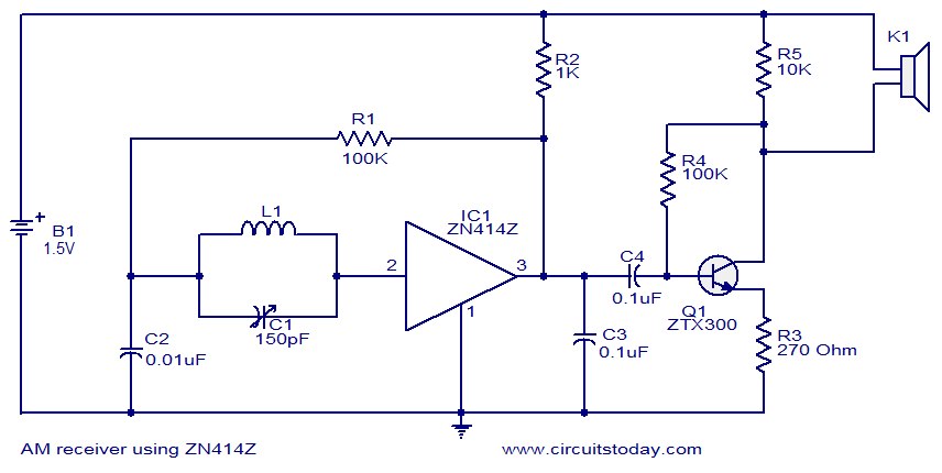
This circuit diagram represents a simple single-chip AM radio, designed around the ZN414Z integrated circuit (IC), which is a ten-transistor tuned radio frequency receiver. The IC features three leads and is housed in a TO92 package. It incorporates all...
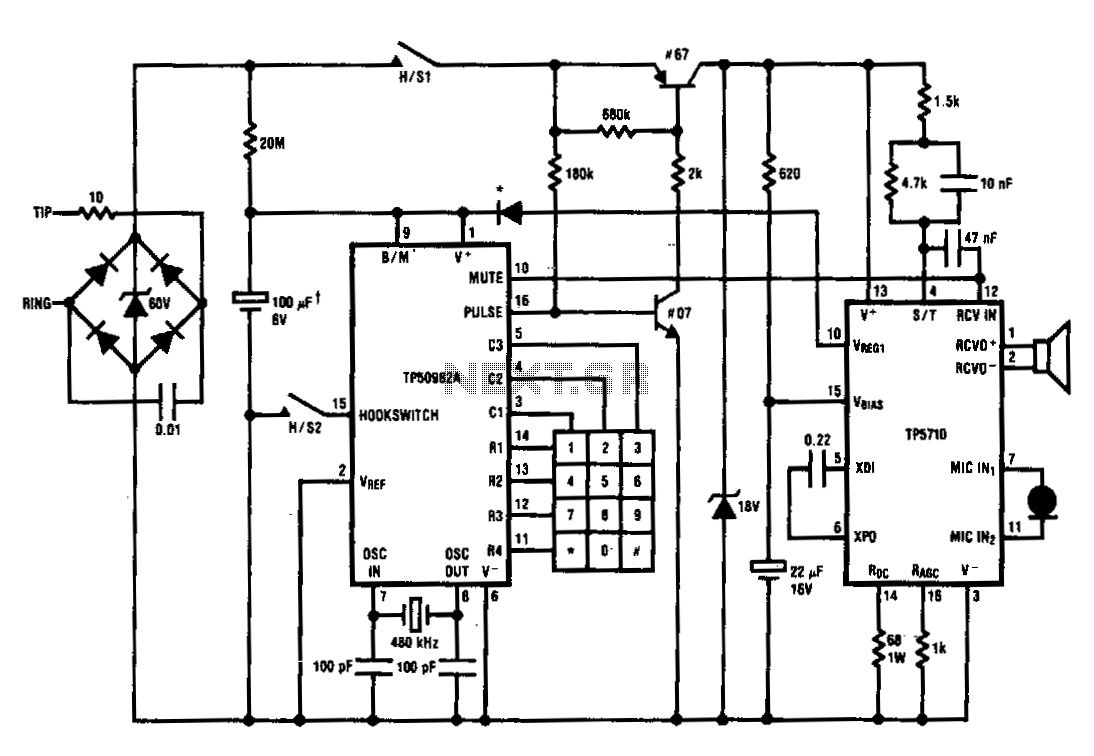
The TP5700 or TP5710 can reduce the number of components required to build a pulse-dialing telephone. The typical current source can be eliminated by utilizing the VREG1 output to power a TP50982A low-voltage (1.7 V) pulse dialer through a...

A simple touch dimmer circuit diagram using the TT6061 IC, which is a touch control integrated circuit used for light dimmer circuits and lamp dimmer circuits. The touch dimmer circuit utilizing the TT6061 IC is designed to provide a user-friendly...
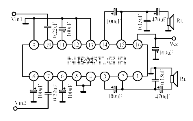
The D2025 is a dual audio power amplifier circuit designed as a stereo audio power amplifier integrated circuit. It comes in a DIP16 package and is applicable for various portable devices, such as tape recorders or portable stereo systems....
A teleremote circuit enables the switching on and off of appliances through telephone lines. It can be used to control appliances from any distance, overcoming the limited range of infrared and radio remote controls. The circuit can switch up...