
Touch Dimmer Circuit for Lamps using TT6061 IC

The touch dimmer circuit utilizing the TT6061 IC is designed to provide a user-friendly interface for controlling the brightness of lamps and lighting fixtures. The TT6061 is specifically engineered for touch-sensitive applications, allowing users to adjust the light intensity with a simple touch, eliminating the need for traditional mechanical switches.
The circuit typically consists of the TT6061 IC, a power supply, a touch sensor, and a load (such as an LED or incandescent lamp). The power supply can range from 100V to 240V AC, which is transformed down to a suitable DC voltage for the operation of the TT6061. The touch sensor is connected to the input of the IC, which detects the touch and sends a signal to adjust the brightness level of the connected load.
The operation of the circuit is straightforward. When a user touches the sensor, the TT6061 IC interprets this input and increases or decreases the brightness of the light accordingly. The IC can be programmed to remember the last brightness setting, providing convenience for users who prefer a specific light level.
Additional features may include a soft-start function to prevent sudden surges in current, which can extend the life of the lamp and enhance user experience. The circuit can also include safety features such as over-voltage and over-temperature protection to ensure reliable operation.
The schematic diagram of the touch dimmer circuit will typically show the connections between the components, including the power supply, the TT6061 IC, the touch sensor, and the load. Proper layout and component selection are crucial to ensure stable operation and minimize electromagnetic interference (EMI), which can affect the performance of the touch sensor.
In summary, the TT6061-based touch dimmer circuit provides an innovative solution for controlling lighting in a convenient and efficient manner, catering to modern lighting applications and user preferences.A simple touch dimmer circuit diagram using TT6061 IC, which is a touch control integrated circuit used for Light dimmer circuit and lamp dimmer circuits.. 🔗 External reference
Related Circuits
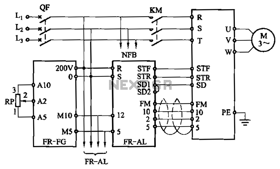
The main speed setting box FR-FG and the linkage setting operation box FR-AL (Mitsubishi inverter) enable synchronous operation of multiple motors. The circuit is illustrated. By utilizing these two external units, the speed of the primary motor (main motor...
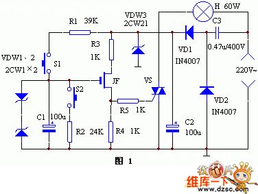
The keyer dimmer table lamp utilizes two touch buttons to adjust the light intensity. When one button is touched, the light dims from a strong brightness, while the other button increases the brightness from a dim state. The working...
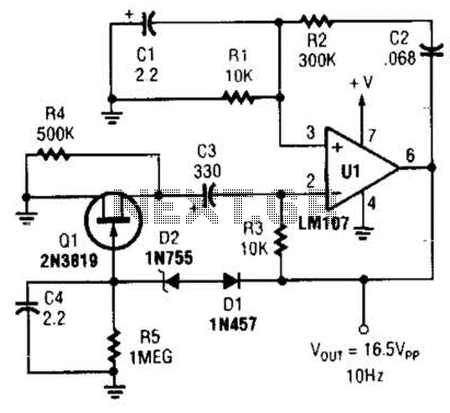
This Wien-bridge sine-wave oscillator utilizes a 2N3819 as an amplitude stabilizer. The 2N3819 functions as a variable-resistance element within the Wien bridge. The Wien-bridge oscillator is a type of electronic oscillator that generates sine waves. It employs a bridge circuit...

This second-order filter, designed for audio applications, utilizes an LM1458 or a similar operational amplifier. It is tunable with a cutoff frequency ranging from 30 Hz to 300 Hz. The resistors R2a and R2b are ganged log-taper potentiometers. The described...
220V AC by Ri buck, Diao. C1 chain ferry flood ear, shouted for the regulator to 12V make C collapse. The film hand touch under ridicule the MT electrode films, clutter body. More: induction signal sent by See Cutting...
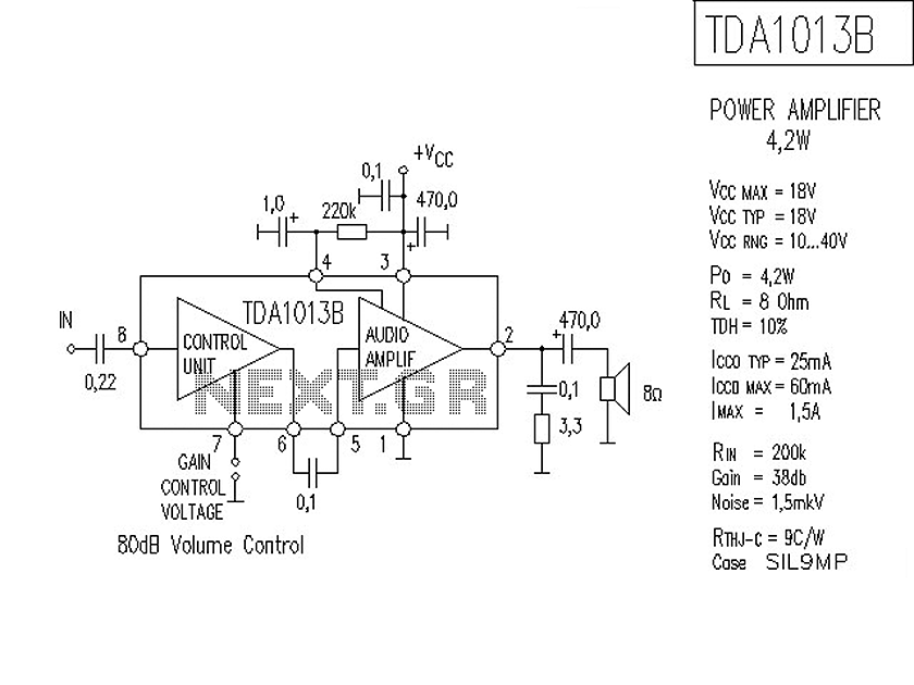
The following is a circuit for a 4-watt audio amplifier. The amplifier utilizes an integrated audio amplifier chip, TDA1013B, which is capable of delivering an audio power output of up to 4W at an 8-ohm load. Its wide supply...