
telephone sharer circuit 9

The described circuit functions as an advanced call handling system that integrates both tone signaling and relay control to manage incoming calls to a specific extension. The initial dialing of the recipient's number establishes a connection without the usual ring-back tone, which is a unique feature allowing for a more seamless user experience. The requirement for the caller to enter an extension number within a specified time frame ensures that the system remains efficient and responsive.
The use of an opto-coupler (MCT-2E) for detecting the ring signal is critical for isolating the control logic from the high-voltage telephone line, enhancing safety and reliability. The 555 timer IC (IC2) is configured in a monostable mode to provide a precise timing mechanism, ensuring that the line is disconnected after 10 seconds if no extension is dialed. The relay (RL10) plays a dual role by providing power to the processing circuitry and disabling the ringer in the exchange, preventing unnecessary ringing.
Upon dialing the extension, the tone receiver (CM8870) accurately decodes the DTMF tones and communicates with the BCD-to-decimal decoder (CD4028), which simplifies the logic needed to control the relay (RL1). The SCR (TH-1) serves as an electronic switch that allows for the control of the 50Hz ring signal. The intentional blocking of half the signal through diode D1 and DIAC1 ensures that only the intended telephone receives the ring, preventing interference with other lines.
Overall, this circuit exemplifies a sophisticated approach to telephone extension management, utilizing common electronic components to create a functional and responsive system for call routing and handling. The careful design considerations, including timing, isolation, and signal processing, contribute to the reliability and effectiveness of the system in a telecommunications environment.For making use of this facility, the calling subscriber is required to initially dial the normal phone number of the called subscriber. When the call is established, no ring-back tone is heard by the calling party. The calling subscriber has then to press the asterik (*) button on the telephone to activate the tone mode (if the phone normally work
s in dial mode) and dial extension number, say, 1`, within 10 seconds. (In case the calling subscriber fails to dial the required extension number within 10 seconds, the line will be disconnected automatically. ) Also, if the dialed extension phone is not lifted within 10 seconds, the ring-back tone will cease.
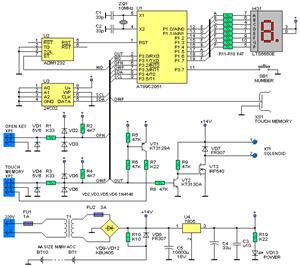
The ring signal on the main phone line is detected by opto-coupler MCT- 2E (IC1), which in turn activates the 10-second on timer`, formed by IC2 (555), and energises relay RL10 (6V, 100- ohm, 2 C/O). One of the N/O` contacts of the relay has been used to connect +6V rail to the processing circuitry and the other has been used to provide 220-ohm loop resistance to de-energise the ringer relay in telephone exchange, to cut off the ring.
When the caller dials the extension number (say, 1`) in tone mode, tone receiver CM8870 (IC3) outputs code 0001`, which is fed to the 4- bit BCD-to-10 line decimal de- coder IC4 (CD4028). The output of IC4 at its output pin 14 (Q1) goes high and switches on the SCR (TH-1) and associated relay RL1.
Relay RL1, in turn, connects, via its N/O contacts, the 50Hz extension ring signal, derived from the 230V AC mains, to the line of telephone 1`. This ring signal is available to telephone 1` only, because half of the signal is blocked by diode D1 and DIAC1 (which do not conduct below 35 volts).
As soon as phone 1` is lifted, the ring current in- creases and voltage drop across R28 (220-ohm, 1/2W resistor) increases and operates opto-coupler IC5 (MCT-2E). This in turn resets timer IC2 causing: 🔗 External reference
Related Circuits
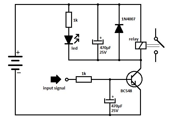
One of the serious problems in relay-operated circuits is the relay clicking or chattering during the on/off operation of the relay driver transistor. This issue can lead to unreliable circuit performance and may cause premature wear of the relay...
Instructions for supervising landscaping projects recommended by satellite relay protection and automatic safety devices. This includes information on the general table for three remote programs related to petrochemical engineering construction, electrical transmission, and the intelligent implementation of community weak...
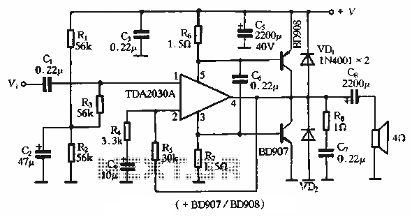
The rDA2030A TDA2030 is an enhanced version of the original product, with a maximum working voltage increased to 18V and a maximum output power of 18W. Additionally, harmonic distortion has been significantly reduced. The application circuit is illustrated. The rDA2030A...
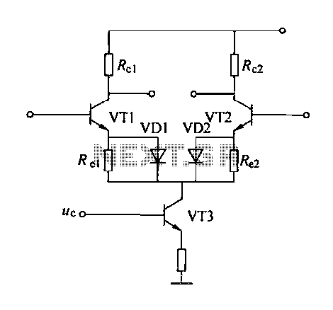
A controllable gain amplifier functions as an automatic gain control circuit within the execution unit. The primary methods for controlling the amplifier's gain involve two approaches: one is by adjusting certain parameters of the amplifier itself, such as emitter...
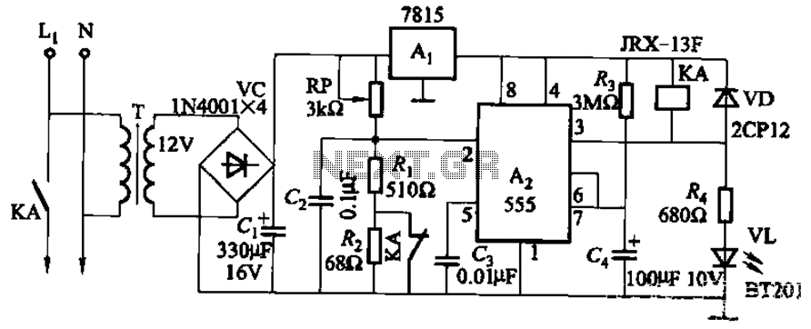
This circuit is applicable in refrigerators and other protective devices. It employs a 7815 three-terminal voltage regulator integrated circuit and an NE555 timer IC configured as a one-shot circuit for delay control. When the voltage drops below 180V, relay...
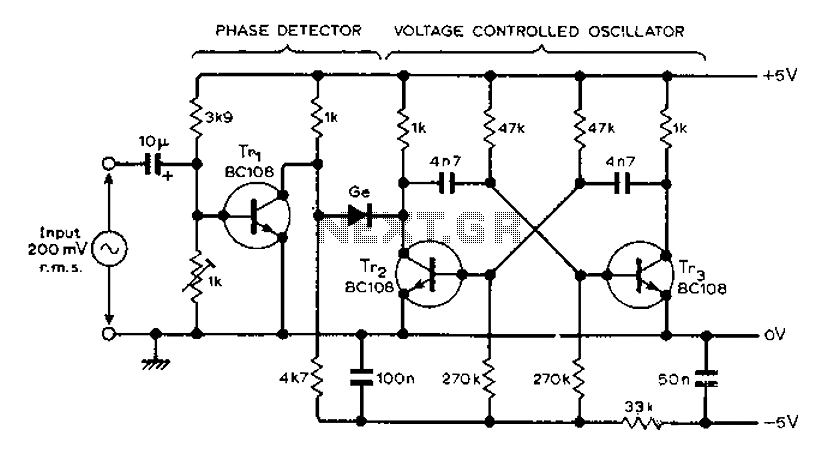
The circuit MVBR utilizes a traditional two-transistor configuration along with other components to create a simple phase-locked loop (PLL). The transistor TR1 and diodes function as a logic gate, activating during half periods of the input waveform of the...