Telephone Switcher

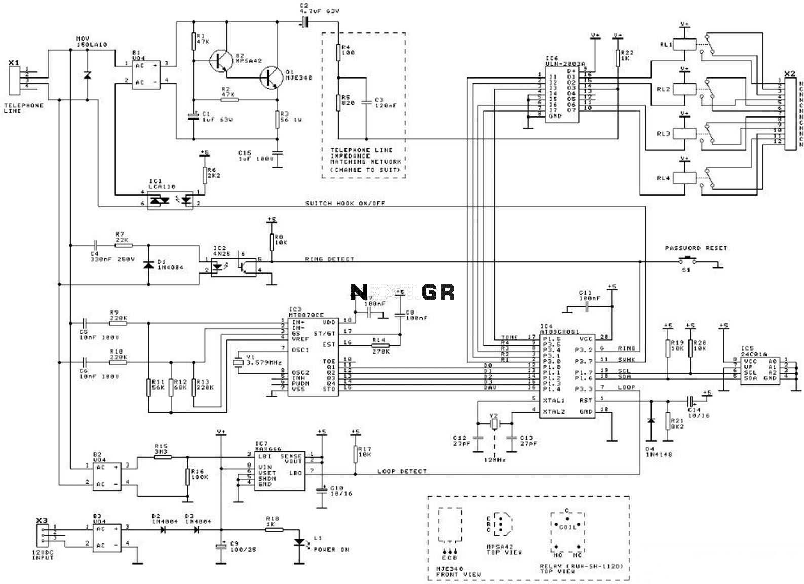
This diagram illustrates the schematic of a telephone switcher that utilizes relays. The device interfaces with the telephone line and allows for remote control of up to four relay outputs through a DTMF (dual-tone multi-frequency) telephone. Several user-configurable settings are available.
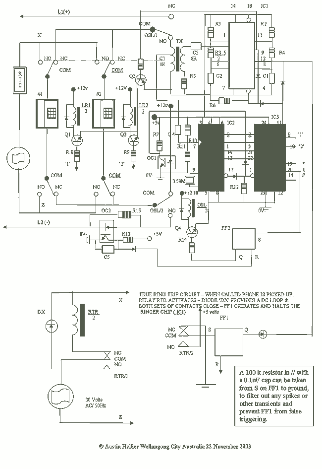
The telephone switcher circuit operates by detecting DTMF signals generated by standard telephone dialing. When a user dials a specific tone sequence, the circuit interprets these tones and activates the corresponding relay outputs. The core components of the circuit include a DTMF decoder, relays, and associated driver circuitry.
The DTMF decoder is responsible for converting the audio frequency signals from the telephone into digital signals that can be processed by the control logic. Commonly used DTMF decoders, such as the MT8870, can decode the 16 different DTMF tones. The output from the decoder is then fed into a microcontroller or a simple logic circuit that determines which relay to activate based on the decoded input.
The relays serve as switches that can control various electrical devices or circuits. Each relay is typically rated for a specific voltage and current, allowing it to safely switch on or off the connected load. The circuit may include flyback diodes across the relay coils to protect the decoder and control circuitry from voltage spikes generated when the relays are de-energized.
User settings can be configured to customize the operation of the switcher, such as setting the specific DTMF codes that correspond to each relay output. This may involve the use of jumpers or dip switches on the circuit board, enabling flexibility in operation according to user needs.
Overall, this telephone switcher circuit is a practical solution for remote control applications, providing an efficient way to manage multiple devices using a standard telephone interface.This diagram is the schematic diagram of telephone switcher using relays. This device connects to the telephone line and can be used to remotely control up to 4 relay outputs using a DTMF (tone dialing) telephone. A number of user settings.. 🔗 External reference


