
Telephone Toll Totalizer

The Telephone Totalizer circuit is designed for ease of use and accuracy in monitoring telephone expenses. The two 4518 dual synchronous up counters facilitate the counting of pulses generated by the oscillator, which reflects the duration of the call. The 74C925 counter serves as the primary counting mechanism, capable of displaying up to four digits, thus allowing for a comprehensive readout of the calculated cost.
The oscillator, operating at a frequency of 100 kHz, generates pulse signals that are fed into the 74C925 counter. This high frequency ensures that the counting mechanism is responsive and accurate, providing real-time feedback on call duration. The typical cost of telephone calls, ranging from 15 to 25 cents per minute, necessitates the use of a clock frequency that aligns with these rates to ensure the calculations remain relevant.
The hex inverting buffer (458) is utilized to ensure that the signals are appropriately conditioned before being processed by the counters. Additionally, the quad 2-input AND gate (4081) plays a crucial role in controlling the flow of signals within the circuit, allowing for precise counting and display operations.
The multiplexed display (DISP 1, 2, 3) is designed to present the calculated cost in a user-friendly manner, allowing users to easily read their estimated telephone charges. The inclusion of a reset switch (S2) provides a simple method for users to clear the previous count, enabling them to start fresh for each new call session.
Overall, the Telephone Totalizer circuit combines various electronic components to create a functional and efficient tool for estimating telephone costs, making it a valuable addition for users looking to monitor their phone expenses accurately. The Telephone Totalizer built around two 4 518 dual synchronous up counters, a 74C925 4-digit counter, a 4 58 4 hex inverting buffer, and a 4 081 quad 2-input AND gate—is fairly simple. Approximate toll charges can be calculated with this counter. It is started when dialing and stopped (manually) on hang-up. It is actually a counter that measures the time you are on the telephone. By calibrating it to the average cost/second of calls (get this from calculations you have done on your monthly phone bill), you can closely estimate your phone bill. The circuit consists of an oscillator running at the 100 000 frequency into the main counter (74C925).
Typically, cost of telephone calls is 15 to 25 cents/minute so that the clock frequency (Ul) is in the 25- to 40-kHz range. U2 and U4 with gates U3 form a ~ 100000 counter. The approximate cost in dollars and cents is read out on the multiplexed display, DISP 1, 2, 3. S2 resets the counter to zero after each use.
Related Circuits

A simple calculator, in conjunction with a chip-on-board (COB) from an analogue quartz clock, is utilized to create a telephone call meter. The calculator facilitates the conversion of STD/ISD calls into local call equivalents and consistently displays the current...
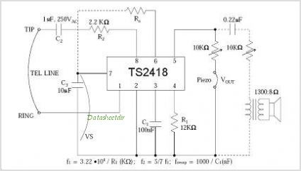
The TS4956 is a comprehensive audio system device featuring three dedicated outputs: one for stereo headphones, one for loudspeaker drive, and one mono output for a hands-free set. The stereo headphone output can deliver over 25 mW per channel...
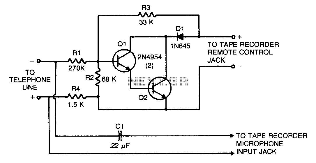
This circuit transforms a tape recorder into a fully automatic device for recording telephone conversations without requiring an external power source. The voltage at the switch terminals of the tape recorder is applied to a pair of Darlington-connected transistors,...

Often, there is a need for an additional telephone ringer in an adjoining room to be alerted about incoming calls. For instance, if the telephone is situated in the drawing room, an extra ringer may be required in the...
A long time ago, when telephones were simple and reliable from an electrical standpoint, telecom operators installed surge protection on all telephone lines at risk from storms. Paradoxically, as modern technology has led to the use of delicate and...
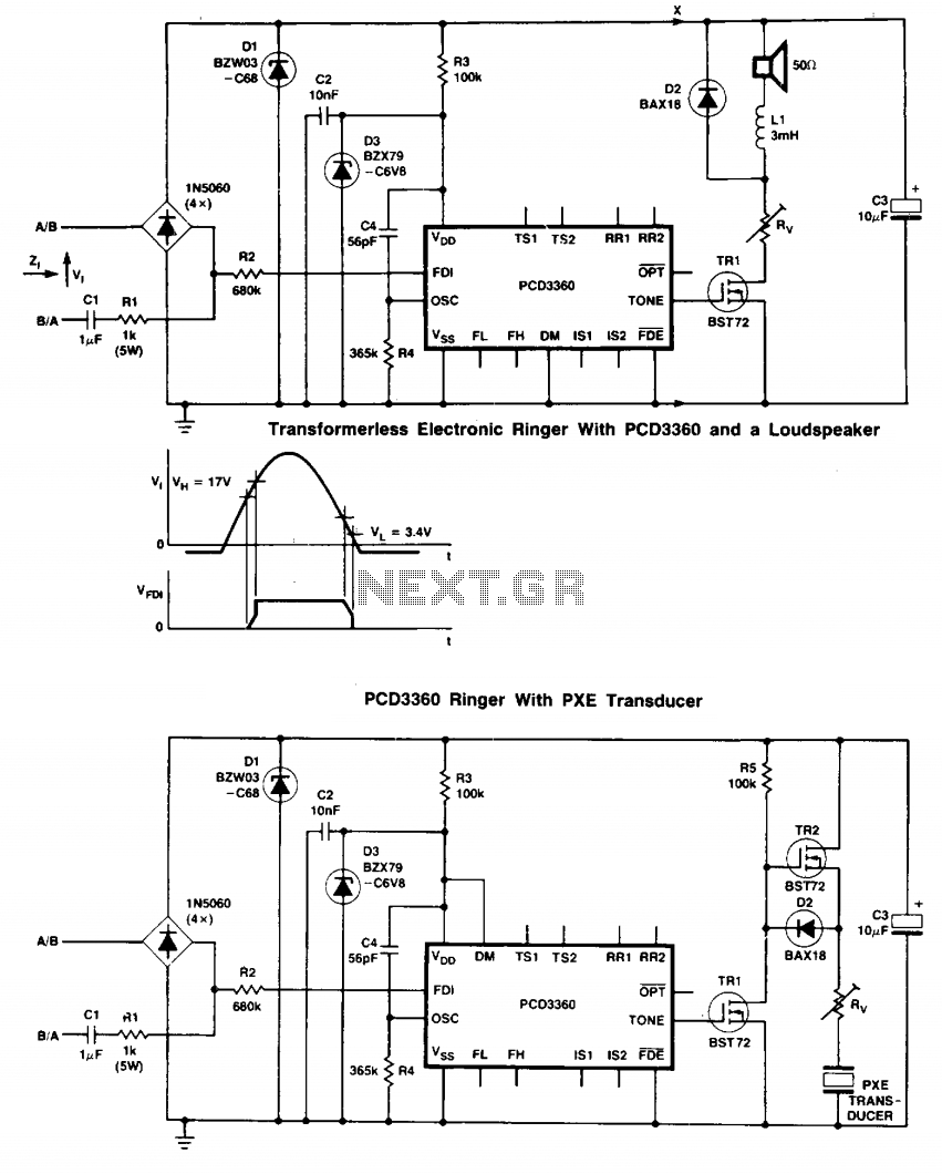
Two BST72 transistors provide an output voltage swing almost equal to the voltage at C3. Pins IS1 and IS2 are inoperative because DM = HIGH. Volume control is possible using resistor Rv. The circuit utilizes two BST72 transistors configured to...