
Telephone Line Simulator Schematic

Fax Machine as Scanner and Printer.
LineSim lets your fax machine function both as a monochrome full-page scanner and as a high-resolution printer. If a scanner is not available, LineSim can link your fax machine to your modem, allowing you to scan a paper document or image into your computer by sending it to the PC as a fax. If a good quality printer is not available, LineSim enables your modem to send a document to your own fax machine, resulting in a high-resolution printout. To initialise a connection, just set the fax or PC to dial any arbitrary number (or no number). You may have seen overpriced units advertised offering 'fax as scanner / printer' facilities, however these do not provide either dialling tones or a ringing signal. Consequently, you must set your modem for blind dialling and use your fax machine and modem in manual receive mode. (If this is all you require, click here.) Conversely, LineSim simulates a conventional telephone call, producing all the required tones and signals, thereby allowing normal dialling and automatic answering. If you need to program several numbers into a telephone and do not have its manual, it may take some trial and error to discover how to program it. Some telephones have to be off-hook in order to be programmed, thus leaving your line effectively engaged. Instead just connect your telephone into LineSim and program it at your leisure, leaving your line free for incoming calls on your other extensions. The circuit is centred on two cascaded binary counters clocked by a 555 astable multivibrator. Several of the counters' outputs provide the frequencies, tones and time delays required. A pair of operational amplifiers detect on / off hook conditions at both ends of the simulated line. To detect call answering, a third op-amp monitors the ringing current. R/S latches and logic gates provide event storage and signal control. Discrete circuits provide the voltage multiplication and DC to AC conversion required for the ringing signal. A pair of miniature relays, switch each end of the simulated line between connection and ringing.
The LineSim circuit is designed to facilitate the simulation of telephone calls between two local devices without the need for actual telephone lines. This is achieved through a series of interconnected components that replicate the necessary signaling and functionalities of a traditional telephone system. The core of the system is built around two cascaded binary counters, which are driven by a 555 timer configured in astable mode. This configuration allows for the generation of the required clock signals that dictate the operation of the counters.
The outputs from the binary counters are utilized to create various frequencies and tones that are essential for simulating the dialing process and the ringing signal. The system employs operational amplifiers to monitor the on-hook and off-hook states of the connected devices, ensuring that the simulation accurately reflects the conditions of a real telephone line. A dedicated operational amplifier is employed to detect the ringing current, which is crucial for signaling when a call is being received.
To manage the state of the simulation, R/S latches and logic gates are incorporated into the design. These components are responsible for storing events and controlling the flow of signals within the circuit. The use of discrete circuits for voltage multiplication and DC to AC conversion is vital for generating the ringing signal, which is an important aspect of the simulation.
Miniature relays are utilized at both ends of the simulated line to switch between the connection state and the ringing state, allowing for a seamless transition that mimics real-world telephone operations. This setup not only provides an effective means of demonstrating telephony equipment but also allows for versatile uses such as enabling a fax machine to function as both a scanner and a printer, thereby enhancing the overall functionality of the setup.The following text describes construction, testing and use of an electronic telephone line simulator of my own design. This self-build project can simulate a telephone call / connection between any two local telephone devices.
This for a fraction of the outlay of some commercial units, many with cost-increasing features that usually are not required. LineSim makes all the following actions possible without occupying a telephone line or incurring any call charges.
At some time, you must have wanted to do at least one of these things. If your work requires you to demonstrate any form of telephony equipment, LineSim can make it a breeze. No need to have one or even two telephone lines available, just connect your equipment to LineSim and away you go!
Fax Machine as Scanner and Printer. LineSim lets your fax machine function both as a monochrome full-page scanner and as a high-resolution printer. If a scanner is not available, LineSim can link your fax machine to your modem, allowing you to scan a paper document or image into your computer by sending it to the PC as a fax.
If a good quality printer is not available, LineSim enables your modem to send a document to your own fax machine, resulting in a high-resolution printout. To initialise a connection, just set the fax or PC to dial any arbitrary number (or no number). You may have seen overpriced units advertised offering 'fax as scanner / printer' facilities, however these do not provide either dialling tones or a ringing signal.
Consequently, you must set your modem for blind dialling and use your fax machine and modem in manual receive mode. (If this is all you require, click here.) Conversely, LineSim simulates a conventional telephone call, producing all the required tones and signals, thereby allowing normal dialling and automatic answering.
If you need to program several numbers into a telephone and do not have its manual, it may take some trial and error to discover how to program it. Some telephones have to be off-hook in order to be programmed, thus leaving your line effectively engaged.
Instead just connect your telephone into LineSim and program it at your leisure, leaving your line free for incoming calls on your other extensions. The circuit is centred on two cascaded binary counters clocked by a 555 astable multivibrator. Several of the counters' outputs provide the frequencies, tones and time delays required. A pair of operational amplifiers detect on / off hook conditions at both ends of the simulated line. To detect call answering, a third op-amp monitors the ringing current. R/S latches and logic gates provide event storage and signal control. Discrete circuits provide the voltage multiplication and DC to AC conversion required for the ringing signal.
A pair of miniature relays, switch each end of the simulated line between connection and ringing. 🔗 External reference
Related Circuits
This project is designed for individuals with large homes, expansive gardens, and young children. It is a telephone ringer that enables any mains-powered device to operate in response to the ringer of a fixed-line telephone. This device can control...
This application note provides valuable PC board layout, bypassing, and decoupling guidelines for customers who are implementing high-speed data converters in their designs. High-speed data converters are critical components in modern electronic systems, requiring careful consideration of their integration into...
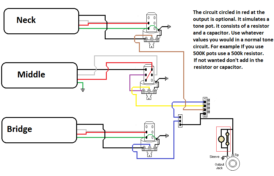
The pickups are connected to individual volume controls that feature push/pull functionality for coil tapping. They are routed to a 5-way switch before reaching the output jack. Additionally, a switch is desired to control the bridge pickup's activation when...

When USB power is present and the device needs to operate, VSupply is supplied directly by the USB, while a PMOS transistor isolates the battery from the supply. Resistor R3 ensures that the PMOS remains on when USB power...
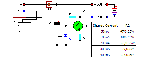
A low-cost solution for charging both NiCd and NiMH batteries is presented. The circuit diagram illustrates a universal charger designed for these battery types. The circuit for the low-cost universal charger for NiCd and NiMH batteries typically incorporates several key...
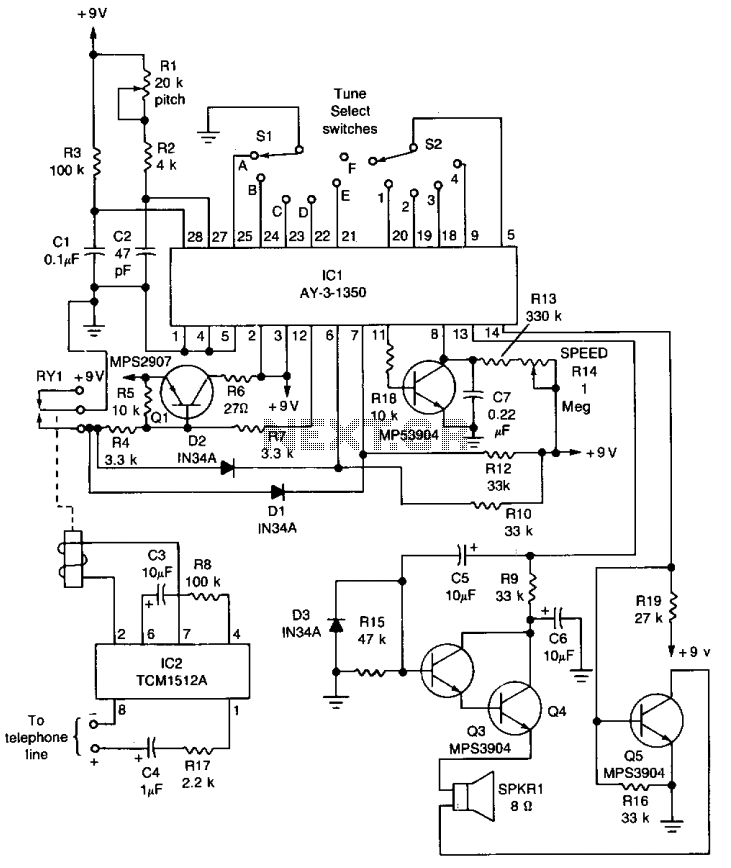
The core component of the circuit is IC1, the AY-3-1350 melody synthesizer IC from General Instrument. IC2 is a TCM1512 telephone ring detector IC powered by the telephone line. The circuit operates when IC2 detects a ring pulse on...