
temp control fan hardware

The temperature-controlled fan circuit is designed to operate from a 15V AC power supply, which can be converted to a 15V DC supply using a rectifier. The triac or SCR used in the circuit is responsible for controlling the fan's operation in response to temperature changes. When rectifying AC to DC, it is essential to consider the voltage drop across the rectifier diodes, which may result in a slightly lower DC voltage than expected.
The proposed configuration involves replacing the MOC3011 with a general-purpose optocoupler, such as the PC817 or MCT2E. The optocoupler's LED should be connected in the same manner as in the original schematic to ensure proper operation. The optocoupler's output can then be connected to the gate of the triac, allowing for effective control of the fan. Pin configurations of the optocoupler should be verified against the datasheet to ensure accurate connections.
In the case of using a DC power supply, the bridge rectifier can be omitted, simplifying the circuit design. The fan should be compatible with the chosen power supply type, whether AC or DC. If a DC fan is selected, a power MOSFET may be employed to control the fan's speed effectively. The fan's wattage must be considered to ensure that the selected components can handle the required load.
The multiplexed seven-segment LED display connected to Port0 of the microcontroller should be wired according to the specified connections, allowing for clear visual feedback on the circuit's operation. The microcontroller's programming will control the fan based on the temperature readings, ensuring optimal performance.
In summary, careful consideration of the power supply type, component selection, and circuit connections will lead to a successful implementation of the temperature-controlled fan circuit.Make this temperature controlled fan and since i am using 15V AC power supply instead of 230V AC. what i want to know is if i would have to change the triac and the resister shown in the diagram below and also if i can use MOC3041 Triac driver optoisolator (RC) instead of MOC3011 the chances are that the opto isolator/driver may not work at such low voltages. the triac will work. you can get rid of the MOC3021/11/41, if you can rectify the 15 VAC into DC and directly use the triac (or SCR) with 1K resistor to its gate and use a normal optocoupler like PC817 or MCT2E thankyou for your reply arun. but from this all i understand soo far is to keep everything in the circuit and replace the MOC3011 with optocoupler as shown in the diag below.
what i dont understand is to where to put the rectifier on the circuit. I mean if i convert the ac to dc, what value of dc would this give me and if i am converting ac into dc then can i use both ac and dc fans i was just wondering if the rectifier converts the 15Vac into 15Vdc can i just use a 15V or something dc power supply and remove the rectifier from the circuit and also on ur diagram above u have 5pins for the optocoupler. pin5 for +5V dc, pin4 going into resistor and what about the rest, is pin1 going into the port 22 of the microcontroller and where are the rest of the pins going Yes, if you use DC supply for fan then you can remove the bridge ( but you first said you had 15V AC ).
The LED part of the optocoupler in my diagram should be connected the same way its in your original schematic. and you don`t have to connect the pin 6 ( collector), leave it floating. I think you have to be clear in what you intend to do, you had first said you have a 15V AC supply for fan and now you are saying you have 15VDC supply - if the latter is true then you can simply use a power mosfet to run the DC fan ( BTW you haven`t said anything about fan`s wattage).
im very sorry if i have not made it clear about my power supply. basically i am still thinking about the power supply and which one to use. looking at my options now. i think i should use a 15V dc power supply as i wont have to use the bridge. this also means i should use a 15V dc fan. So u mean the circuit should look like this below if i am using 15v dc power supply and 15v dc fan. or you can make use of dc motor driver like L293D (see tutorial for more information) its easy to use and controls motor over good range of voltage and current. i also noticed that u said that the led part of the optocoupler should be connected in the same way as it was with the moc3011.
but in moc3011 on the left hand side, the upper pin(pin1) is going to 5v dc and the lower pin2 one going to port22 of 8051. pin6 into triac and pin4 into resistor. but in optocoupler pin4 is connected to the resistor which is connected to triac and pin5 is connected to 5v DC.
and im assuming the pin2 is going into port22 of 8051 and pin1 to 5v dc if i am right digital guy, you can use any general opto like : PC817, MCT2E, 4N25, . etc if you have any other opto on hand then search for its datasheet to know its pin out. i was just wondering if the assembly code for the circuit will be the same for the circuit with moc3011 and 203V ac power supply at ( and it will work in the same way and have the same features.
i just wanted to ask how i should connect it in the same way as the diagram below. there are no pin letters ( a, b, c etc) and there seem to be no dp pin as only 7 lines from microcontroller are used. i am using a breadboard. in the above schematic the multiplexed seven segment LED display is connected to Port0, about the connections- port0.
0 is connected to segment "a", port0. 1 to "b". so on upto port0. 6 which is connected to "g". since the dp is not used port0. 7 is left unconnected. this part of the circuit is attached to port 13 of the 8051. and if i am not mistaken it just converts 230V ac into 5v 🔗 External reference
Related Circuits
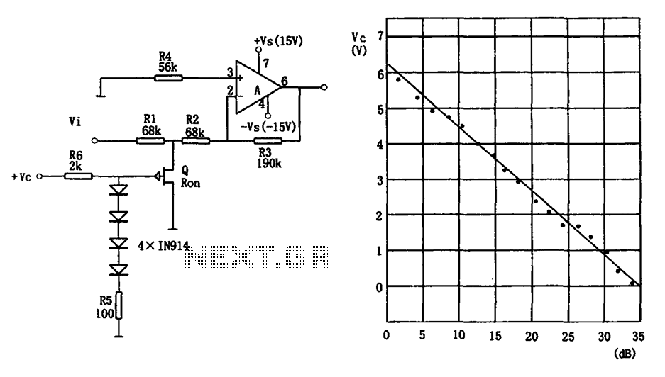
The voltage-controlled gain amplifier utilizes a FET gate voltage and the drain-source resistance (RSD) to approximate a logarithmic relationship. The integrated circuit chip LM307 is employed in the amplifier circuit with the inverting input configuration. In the circuit, RSD...
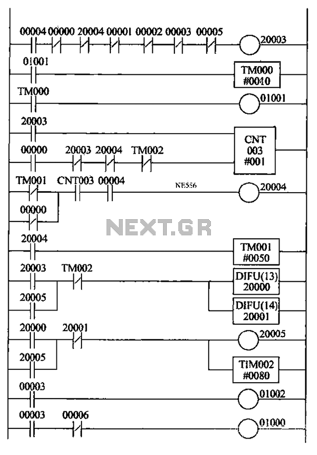
An automatic reclosing PLC control program has been developed based on the specifications for automatic reclosing devices and PLC I/O definitions. The design includes a ladder-shaped diagram with the following features: 1) When the circuit breaker closes, the K4...
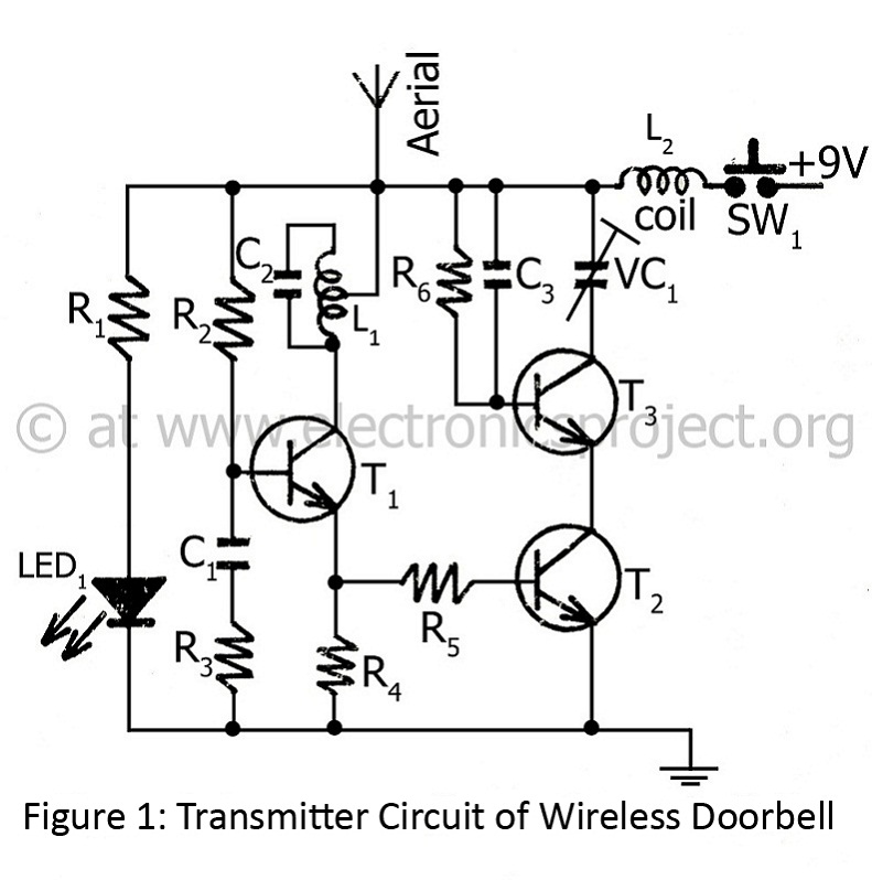
The controlling range of the wireless doorbell is 100 meters. The transmitter section is designed around an oscillator transistor (BF194B) T2, which is followed by two transistors (BC148) T1 and T3. Transistor T2 generates a specific radio frequency determined...
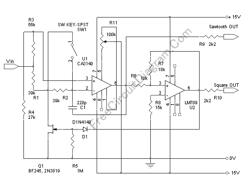
This voltage-controlled oscillator circuit is compact and exhibits good linearity. The precision can be better than 0.01% if properly constructed. The circuit provides three different output waveforms: square, triangle, and sawtooth, which are essential for music synthesizers and measurement...
The following diagram illustrates the circuit of a 20-band stereo graphic equalizer, which is designed to control audio signals within specific frequency ranges. This circuit should be connected prior to the amplifier circuit. For optimal performance, it is recommended...
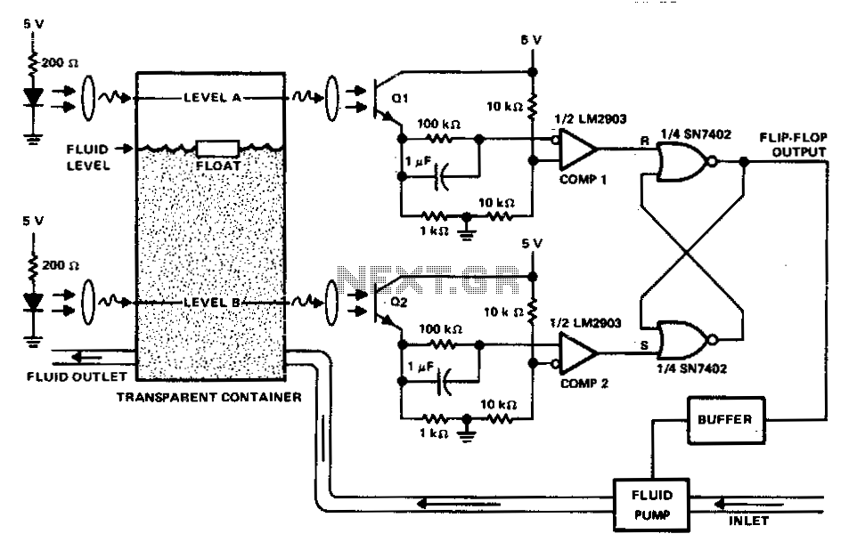
This circuit can be used to maintain fluid between two levels. Variations on this control circuit can be made to keep something that moves within certain boundary conditions. The described circuit functions primarily as a fluid level control system, designed...