
Temperature controlled DC fan

This circuit employs a thermistor as a temperature sensor, which is a resistor that changes its resistance with temperature variations. In this application, the thermistor (R1) is connected in such a way that its resistance decreases as the temperature increases. This change in resistance affects the base current flowing into Q1 (BC 547), a general-purpose NPN transistor.
When the temperature rises, the thermistor's resistance drops, allowing more current to flow into the base of Q1. This increased base current results in a higher collector current, which in turn lowers the collector-emitter voltage (Vce) of Q1. The collector of Q1 is connected to the base of Q2 (BD 140), a PNP transistor. As the collector voltage of Q1 decreases, it increases the forward bias on Q2, allowing it to conduct more current from its emitter to collector. This increased current through Q2 drives the 12 V DC fan at a higher speed.
The operation of the fan is directly proportional to the temperature, offering a simple yet effective way to control fan speed. Additionally, an LED can be included in the circuit to provide a visual indication of the fan speed. The brightness of the LED will vary in accordance with the fan speed, providing a simple feedback mechanism to the user. The circuit can be powered with a 12 V supply, and proper biasing resistors should be selected for both transistors to ensure they operate within their specified limits. Proper thermal management should also be considered, especially if the circuit is to be used continuously.Here is a simple circuit based on two transistors that can be used to control the speed of a 12 V DC fan depending on the temperature. A thermistor (R1) is used to sense the temperature. When the temperature increases the base current of Q1 (BC 547) increases which in turn decreases the collector voltage of the same transistor.
Since the collector of Q1 is coupled to the base of Q2 (BD 140), the decrease in collector voltage of Q1 forward biases the Q2 more and so do the speed of the motor. Also, the brightness of the LED will be proportional to the speed of the motor. 🔗 External reference
Related Circuits

This circuit will disconnect the line supply to audio or video equipment if there has been no input signal for approximately 2 seconds. Switch SI provides manual operation, while switch S2 functions as a reset mechanism. This circuit allows...
The LM35 temperature sensor provides an output of 10 mV/°C for every degree Celsius over 0°C. At 20°C, the output voltage is 20 x 10 = 200 mV. The circuit consumes 60 µA. The load resistance should not be...
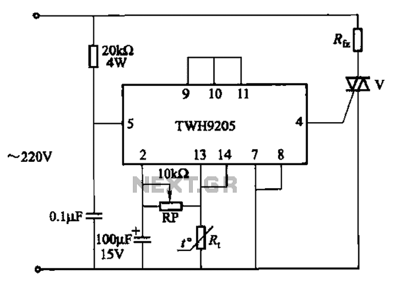
This circuit is used for temperature control in various heating equipment such as water heaters, microwave ovens, air conditioners, refrigerators, fans, and automatic fire extinguishing devices. It includes a negative temperature coefficient (NTC) thermistor as the temperature sensing element...
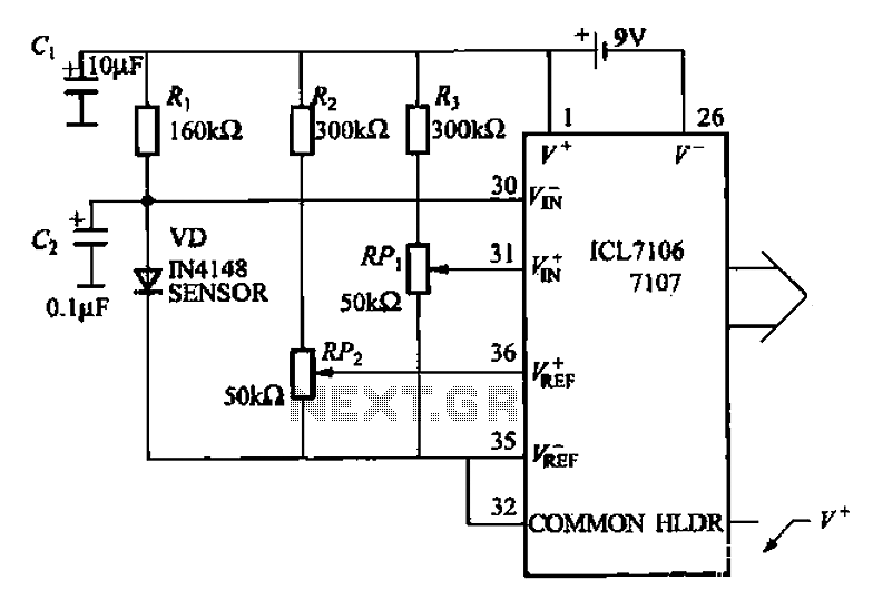
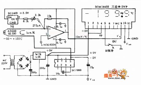
A diode temperature sensor is utilized in a 3-digit thermometer, featuring a 3-digit A/D converter and display driver IC L7106/7107. This configuration amplifies the signal, performs A/D conversion, and executes a series of decoding and display driver processes to...
This circuit allows for the adjustment of a fan's speed from a distance, such as from a couch or bed. It utilizes an infrared receiver module TSOP1738 to capture the infrared signals sent by a remote control. The circuit...

The diagram illustrates a block diagram for an agenda alarm and agenda thermometer system. It includes one temperature sensor, a real-time clock (RTC), a microcontroller (PIC), an EEPROM, a 7-segment display, and a keyboard. The EEPROM is utilized to...