
Temperature Controlled Relay Circuit

The temperature-controlled relay circuit operates by monitoring the ambient temperature using a temperature sensor, such as an NTC thermistor or a thermocouple. The sensor provides an analog voltage or resistance change that correlates to the temperature. This signal is fed into a comparator or microcontroller that compares the sensed temperature against a predefined setpoint.
When the sensed temperature exceeds the setpoint, the comparator output changes state, activating a relay. This relay can control larger loads, such as heaters or cooling systems, by switching them on or off based on the temperature readings. The relay's contacts can handle the necessary current and voltage for the application, ensuring safe operation.
The circuit may include additional features such as hysteresis to prevent rapid on-off cycling of the relay, which can prolong the lifespan of the relay and improve system stability. A potentiometer can be used to adjust the setpoint, allowing for flexibility in temperature control.
Furthermore, a LED indicator could be incorporated to visually indicate the status of the relay, providing an intuitive understanding of the circuit's operation. Power supply considerations must also be taken into account, ensuring that the circuit operates within the specified voltage range for all components involved.
In summary, this temperature-controlled relay circuit is a versatile solution for applications requiring precise thermal management, offering reliable performance and ease of integration into various systems.This temperature controlled relay circuit is a simple yet highly accurate thermal control circuit which can be used in applications where automatic tempera.. 🔗 External reference
Related Circuits
The foot 13 between valve value 1 and valve value 2 will draw the transistor base current. If the relay releases, after a recovery time of 0.5 seconds, pressing the key will initiate the switching process again. The timer...
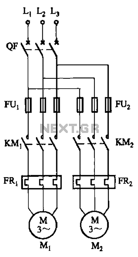
The circuit illustrated in Figure 3-64 operates with switch SA1 in the work position and switch SA2 in the standby position, allowing motor Mi to run while motor Mz remains on standby. In the event of downtime for motor...
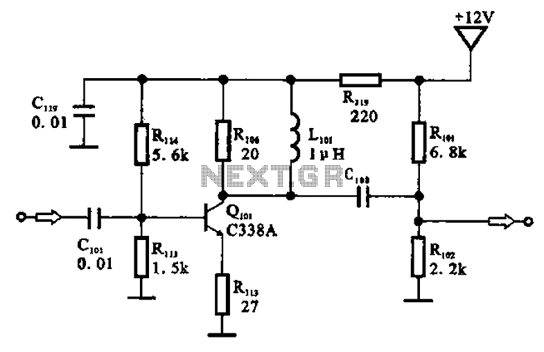
The amplifier circuit is designed as a pre-amplifier configuration. It utilizes transistor Q101 and other components such as inductor L101 and biasing elements. The transistor operates as a common emitter intermediate frequency (IF) amplifier. The IF signal is coupled...
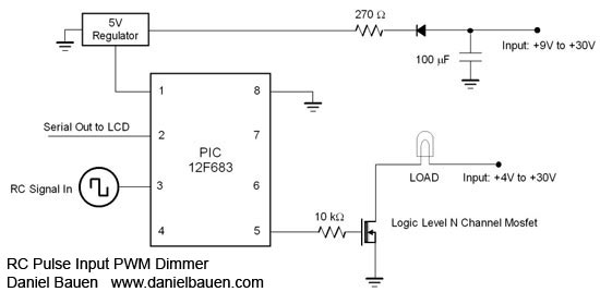
A PIC12F675 microcontroller can switch up to five outputs sequentially using a standard Remote Control pulse input ranging from 1 to 2 ms. While any RC channel input can be utilized, it is particularly effective when paired with rotary...
The current generated flows through clips placed on the earlobes. The output current is adjustable from 80 to 600 microamperes, following the recent launch in Europe. The described device utilizes a current generation mechanism that delivers a controlled microcurrent through...
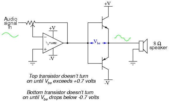
This project is an audio amplifier designed to amplify output signals from small radios, tape players, CD players, or other audio signal sources. For stereo operation, two identical amplifiers must be constructed—one for the left channel and another for...