
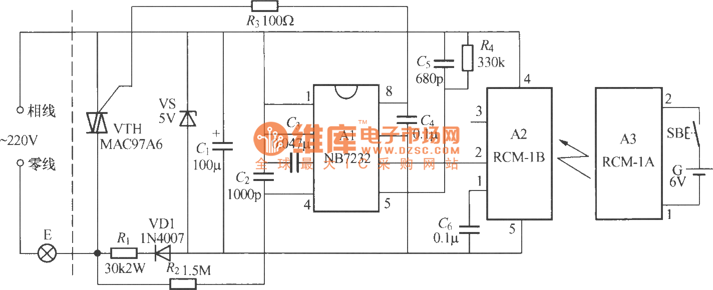
Timer circuit with 106 fixed preset time

The described circuit includes a relay mechanism controlled by a transistor switch, where the activation of the relay is contingent on the charging of a capacitor and the subsequent pressing of a key. The TCA965 window discriminator functions as a critical timing component, ensuring accurate delay intervals for the relay operation.
In this configuration, the capacitor C is charged through a resistor network upon pressing the key Ta. The charging time is dictated by the RC time constant, which is essential for determining how quickly the voltage across the capacitor reaches the threshold necessary to turn on transistor T1. Once the voltage is sufficient, T1 activates, allowing current to flow through the relay coil, thereby engaging the relay contacts.
The recovery time of 0.5 seconds is an important parameter, as it prevents immediate retriggering of the relay after it has been released. This delay is implemented to ensure stable operation and to avoid potential bouncing issues that could arise from mechanical relay contacts.
The schematic would typically illustrate the connections between the TCA965, the capacitor, resistors, and the transistor T1, along with the relay. The input from the key Ta would be shown as a momentary switch that, when pressed, completes the circuit and begins the charging process of capacitor C. The output side would display the relay contacts, indicating the load that is controlled by the relay.
In summary, this circuit effectively utilizes a combination of a window discriminator, a capacitor, and a transistor to control a relay with a specified recovery time, ensuring reliable operation in response to user input.The foot 13 between valve value 1 and valve value 2 will suck the transistor base current. If relay releases, after recovery time 0.5s, to press key then it will start to switch process again. The timer is composed ofwindow discriminator TCA965 to. After pressing the key Ta, decision time capacitance C will charge. transistor T1 obtains base curren.. 🔗 External reference
Related Circuits
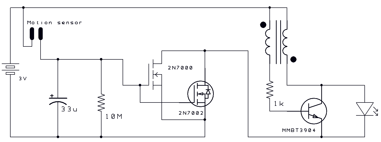
Two thoughts on a motion-activated Joule Thief LED bike light. The circuit for switching on and delayed switch-off is simple. The motion-activated Joule Thief LED bike light utilizes a straightforward circuit design that capitalizes on the principles of energy conservation...
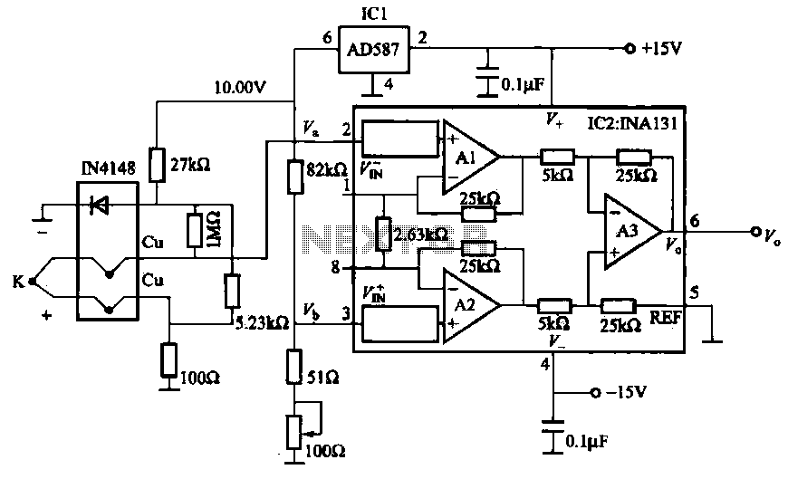
The AD587 is a precision voltage reference providing a 10 V output, generated using a 27 kΩ resistor along with a compensation diode (1N4148) and a thermocouple. This setup connects to the VI + N terminal of a differential...
This 555 timer circuit toggles a relay when a button is pressed. Pins 2 and 6, which are the threshold and trigger inputs, are maintained at half the supply voltage by two 10K resistors. When the output is high,...
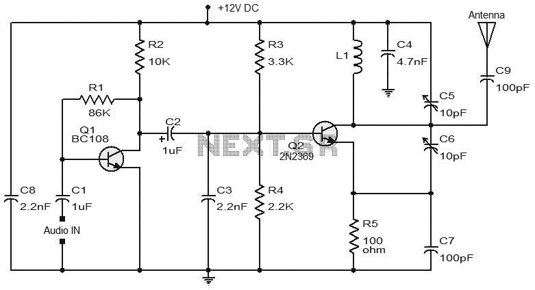
Numerous FM transmitter circuits have been published, and this is another example of a simple two-transistor FM transmitter. The first stage of the circuit is a preamplifier based on transistor Q1. This stage operates as a collector-to-base biased amplifier,...
The diagram above illustrates a radio remote control dimmer circuit. This circuit utilizes a micro radio transmit/receive module in conjunction with a light modulation ASIC, resulting in a compact and easily producible design. It operates reliably and features a...
This is a nice design for people who have no tachometer in the car or on the bike. The circuit uses two ICs: an NE 555 and a CA 3140. The input of the circuit is connected to the...