
Temperature Relay Circuit

The temperature relay circuit operates by monitoring the temperature in a designated area and providing a signal when a predefined temperature threshold is exceeded. The primary components of this circuit include a thermistor or temperature sensor, a relay, a potentiometer (P1), and a transistor (T1).
The thermistor serves as the temperature sensing element. It changes its resistance based on the ambient temperature, allowing the circuit to detect temperature variations. The relay acts as a switch that can control larger loads, such as alarms or fans, based on the signal received from the transistor.
P1, the potentiometer, is used to set the desired temperature threshold. By adjusting P1, the user can calibrate the circuit to respond at a specific temperature level. The transistor (T1) is configured as a switch that is activated when the voltage across the thermistor reaches a certain level, indicating that the temperature has exceeded the setpoint.
The circuit can be powered using a DC power supply, and it is advisable to include a diode in parallel with the relay coil to prevent back EMF when the relay is deactivated. This configuration enhances the reliability and longevity of the circuit components.
This temperature relay circuit is suitable for various applications, including fire alarm systems, HVAC systems for temperature control, and other monitoring systems where temperature regulation is critical. Proper layout and component selection will ensure accurate temperature detection and reliable operation of the relay.This simple temperature relay circuit can be used to signal a fire or setpoint for temperature monitoring function. You need to adjust P1 so that T1`s base.. 🔗 External reference
Related Circuits
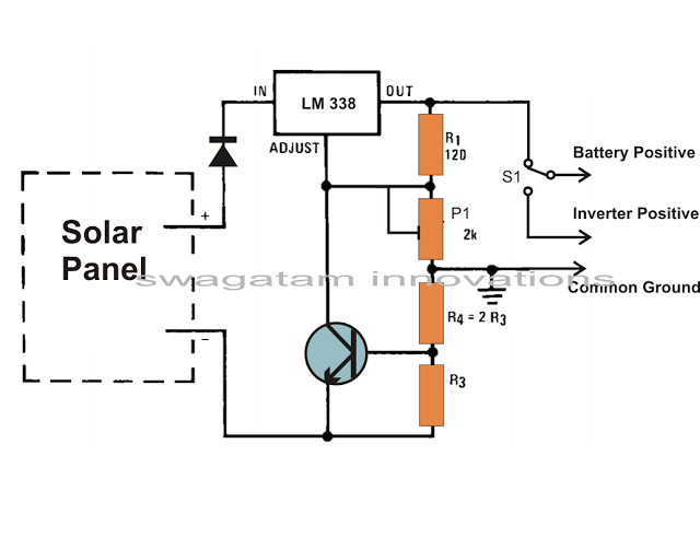
Solar panels are well-known devices that convert solar energy or sunlight into electricity. A solar panel consists of discrete sections of individual photovoltaic cells, each capable of generating a small amount of electrical power, typically between 1.5 to 3...
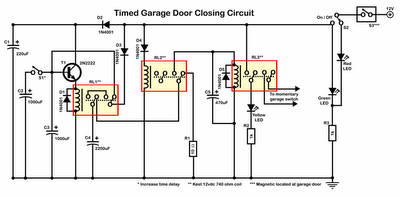
Timer garage door circuit schematic diagram, printed circuit board. The timer garage door circuit is designed to automate the opening and closing of a garage door based on a predetermined time interval. The schematic diagram illustrates the layout and connections...

An audio power amplifier circuit for a 3-watt stereo amplifier using the MAX 7910 IC is explained below. The audio power amplifier circuit utilizing the MAX 7910 IC is designed to deliver a maximum output power of 3 watts per...
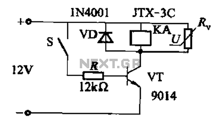
In a concrete circuit relay application, the transistor VT functions as a high-speed, high-voltage switch. The voltage requirement for switching is 5 to 10 times the rated voltage of the solenoid valve. The circuit is designed for a fast...
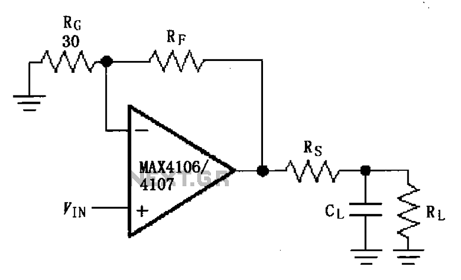
The MAX4106/4107 is designed with a capacitive load drive circuit that includes an isolation resistor (Rs). While the MAX4106/4107 exhibits excellent AC characteristics, they are not optimized for driving high reactive loads. Utilizing a high reactive load may diminish...
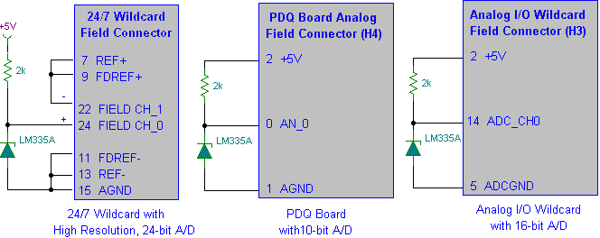
Interfacing the LM335A temperature sensor with A/D converters involves measuring temperature using the LM35 and LM335A sensors alongside the 9S12 HCS12 microcontroller. This process includes analyzing both calibrated and uncalibrated temperature errors of integrated circuit temperature sensors. The LM335A is...