
Temperature Sensing and Control

The temperature indication and control system based on the AD596/AD597 integrates a thermocouple sensor to measure temperature variations accurately. The AD596 and AD597 are precision analog signal conditioning ICs designed specifically for thermocouple applications, providing a means to convert the low-level thermoelectric voltage generated by the thermocouple into a usable output signal.
In a typical configuration, a thermocouple is connected to the input of the AD596/AD597, which amplifies the small voltage signal and linearizes it according to the specific thermocouple type being used (e.g., Type K, J, T, etc.). The output can then be fed into an analog-to-digital converter (ADC) for digital processing or directly to a microcontroller for real-time temperature monitoring and control.
The system can include additional components such as operational amplifiers for further signal conditioning, filters to remove noise, and microcontroller units (MCUs) for processing the temperature data. The MCU can implement control algorithms to regulate temperature by adjusting heating or cooling elements based on the measured temperature relative to a setpoint.
Power supply considerations are crucial for this system, as the AD596/AD597 typically require a stable voltage supply for optimal performance. Proper PCB layout and grounding techniques should be employed to minimize interference and ensure accurate readings. Overall, this temperature indication and control system is suitable for various applications, including industrial process control, HVAC systems, and laboratory environments, where precise temperature management is essential.This is a temperature indication and control system using the AD596/AD597. In this system, AD596/AD597 is used as a closed-loop thermocouple signal conditioner.. 🔗 External reference
Related Circuits
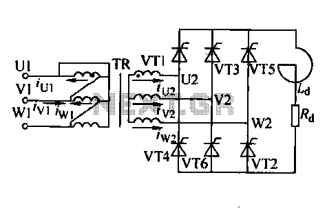
Trigger circuit routing forms include various types such as simple trigger circuits, single-junction transistor trigger circuits, synchronous sine wave trigger circuits, sawtooth transition phase shift (synchronous) trigger circuits, and integrated trigger circuits. This section presents individual cases for introduction...
Based on the classic Baxendall tone control circuit, this provides a maximum cut and boost of around 10dB at 10K and 50Hz. As the controls are passive, the last transistor provides a slight boost. The output is designed to...
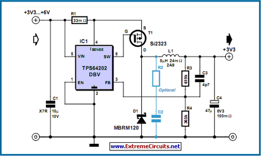
The TPS6420x controller is designed to operate from one to three series-connected cells or from a 3.3 V or 5 V supply obtained from a USB port. At its output, it can produce 3.3 V at 2 A, suitable...
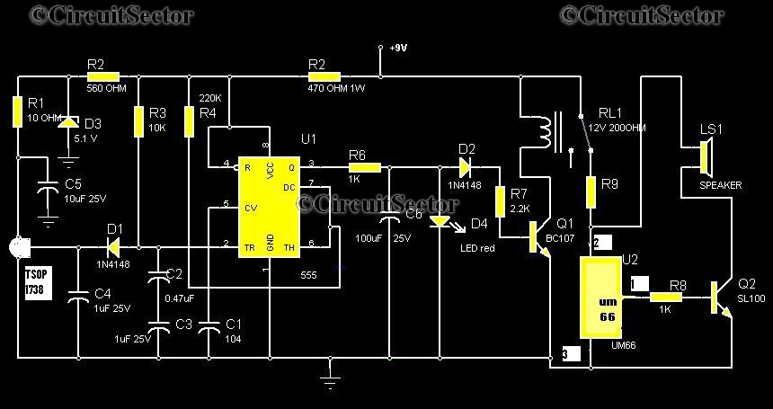
Numerous circuits are available for infrared burglar alarms; however, the transmitter section of these circuits can be complex and may require assembly. This burglar alarm circuit utilizes a standard DVD remote as the transmitter, which reduces both cost and...

The main oscillator is printed in blue and is voltage controlled. In this construction, the VCO range is 88 to 108 MHz. As you can see from the blue arrows, some energy goes to an amplifier and some energy...
The TMP03 is a complete temperature data-acquisition system on a monolithic silicon chip. Including a silicon-based sensor, internal voltage reference, and sigma-delta A/D converter, it fits in a 3-pin (power, common, and output) TO-92 transistor package. Its digital output...