
Three-phase controlled rectifier circuit

The described trigger circuit encompasses several configurations designed to manipulate electrical signals for various applications, particularly in motor control. The TRIAC serves as a key component, allowing for the regulation of power to the motor based on the phase shift induced by the capacitor. The use of a 30W adjustable potentiometer provides flexibility in controlling the output pulse, enabling fine-tuning of the motor's operational speed.
The integration of flip-flop circuits enhances the versatility of the design, allowing for bidirectional control of the motor, which is essential for applications requiring direction reversal. This setup is particularly useful in robotics or automated systems where precise control over motor functions is necessary.
The choice of components is critical for ensuring reliable operation. The main circuit capacitor, rated at 901 F / 600V, must withstand the voltage and provide adequate phase shift for effective control. The selected VT1 transistor, with a rating of 3CTS20A capable of handling voltages between 800 to 1000V, ensures that the circuit can manage the high power requirements of the motor. The fuses FU1 and FU2, rated at 10A, provide necessary protection against overcurrent conditions, safeguarding the circuit from potential damage.
Overall, this trigger circuit design illustrates a sophisticated approach to motor speed control, combining various electronic components and configurations to achieve desired operational characteristics. The modular nature of the design allows for customization based on specific application needs, making it a valuable solution in the field of electronics.Trigger circuit routing forms, such as some simple trigger circuit, single-junction transistor trigger circuit, synchronous sine wave trigger circuit, sawtooth transition phase shift (synchronous) trigger circuit, integrated trigger circuit. For limited space, this section can only include individual cases for the introduction. Introduction to circuit theory t triggered by a sharp pulse output circuit to trigger the TRIAC, turning it on, the capacitor will be 220V single-phase power phase-shift followed by motor t make it work. 30W adjustment potentiometer output pulse trigger line is changed, thereby changing the VT1 conduction angle change given the magnitude of the voltage stator windings, enabling stepless speed regulation.
The circuit may be two sets of flip-flop circuit, triggering the two bidirectional thyristor achieve electric reversing speed control unit. Component parameters: the main circuit capacitor selected phase shift 901, F / 600V. VT1 election 3CTS20A / 800 ~ 1000V, FU1, FU2 election 10A, the rest of the circuit diagram according to preferences.
Related Circuits
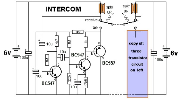
The key to avoiding instability (motor-boating) in a high-gain circuit is to power the speaker using a separate power supply. This circuit design allows for the connection of one or two additional stations. It is recommended to construct the...

Transistors Q1 and Q2, along with resistors R1 through R7, form the input balancing stage that measures the resistance between points X and Y. This stage operates as a bridge circuit, incorporating resistors R1, R2, R6, R7, and the...
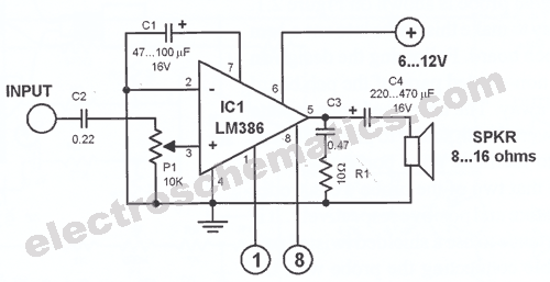
This car stereo booster utilizes an LM2896 integrated circuit, which features two amplifiers. It operates with supply voltages ranging from 3 to 15 volts. The power output is 2.5 watts per channel when connected to an 8-ohm load at...
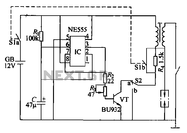
This paragraph describes an easy car alarm circuit that utilizes fewer components and is simple to produce. The circuit consists of an automobile anti-theft alarm system based on the NE555 timer, a power switch (VT), and a switch (S2),...
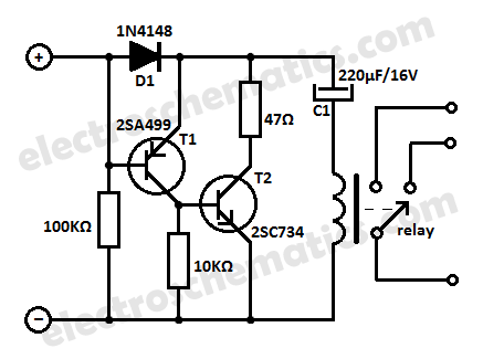
This low current relay circuit is designed for use in battery-operated electronic devices. Its operating current is in microamperes (µA). This is achieved by using a bistable relay and incorporating additional components to enable the relay to function like...
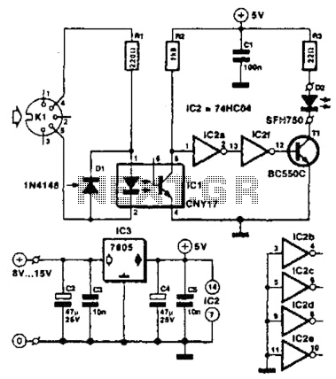
Used for digital control of musical instruments, this transmitter converts digital data signals into equivalent optical signals for a fiber optic cable interface. Optocoupler IC1 provides isolation, driving IC2-a and -b, and T1, ultimately providing a cable driver LED...