
Temperature sensor and DVM interface

The described circuit utilizes a temperature sensor IC (IC1) that converts temperature to a voltage signal. The sensor operates by producing a small voltage output proportional to the temperature in Kelvin, which is then scaled to a more usable range in degrees Celsius. The conversion is facilitated by a resistor (R1) and a variable resistor (VR1) that adjust the output to 10 mV per degree Kelvin, making it suitable for further processing.
The operational amplifier IC2 is specifically chosen for its low power consumption and minimal input drift, ensuring accurate readings over time. The use of a voltage follower configuration in the primary op-amp allows for high input impedance, which prevents loading the sensor and preserves the integrity of the signal. The secondary amplifier's role is crucial for adjusting the output reference voltage, allowing the system to correctly interpret temperatures below freezing by offsetting the readings to account for the absolute zero reference point.
Overall, the output from the two op-amps is a differential voltage that directly correlates to temperature changes, with a sensitivity of 0.01 V per °C. This level of sensitivity is beneficial for applications requiring precise temperature monitoring, such as in HVAC systems, laboratory experiments, or environmental monitoring. The circuit design emphasizes stability and accuracy, making it a reliable choice for temperature measurement applications.The DVM gives a direct indication of the temperature of the sensor in degrees Centigrade. The temperature sensor IC1 gives a nominal 1 µ per degree Kelvin which is converted to 10 mV per degree Kelvin by Rl and VR1. IC2 is a micropower, low input drift op amp with internal voltage reference and amplifier. The main op amp in IC1 is connected as a voltage follower to buffer the sensor voltage at Rl. The second amplifier in IC1 is used to amplify the .2 V internal reference up to 2.73 V in order to offset the 273 degrees below 0°C.
The output voltage of the unit is the differential output of the two op amps and is thus equal to 0.01 V per °C.
Related Circuits

This simple circuit can be used to sense the distance between the rear bumper of a car and any obstacle behind it. The distance is indicated by the combination of LEDs (D5 to D7) that illuminate: at 25 cm,...
Detecting the color of an object can be an interesting and useful electronic application. This can be achieved using a color sensor like the TCS3200 in conjunction with a general-purpose microcontroller such as the AVR ATmega32. The TCS3200 chip...
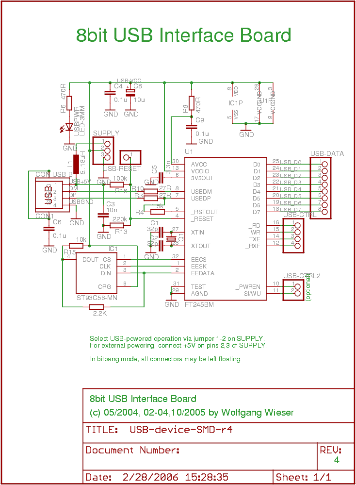
The objective was to create a compact USB interface board that can be easily connected to microcontroller boards. It is designed to support both USB-powered and externally-powered operation. The number of external components has been minimized, although there are...
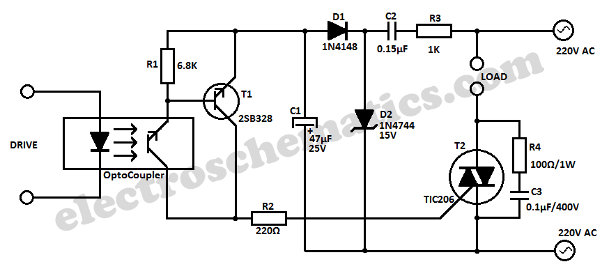
This simple 220V power interface is designed for monitoring electrical equipment and devices using a computer. The interface only detects whether the monitored device is powered on or off. A key feature of this circuit is the galvanic isolation...

The system consists of a MAX1463 precision pressure detection circuit block diagram. The output voltage from the bridge pressure sensor is connected to the MAX1463 inputs IN1+ and IN1-. Controlled by a CPU, the pressure signal undergoes nonlinear calibration...
A color sensor is an engaging project for hobbyists. The circuit is capable of detecting eight colors, including blue, green, and red (the primary colors), as well as magenta and yellow. The color sensor circuit typically employs a photodiode or...