
temperature sensor relay switch circuit

The circuit is designed to monitor and respond to temperature changes, providing versatility in applications such as cooling systems and safety alarms. The use of the BC547B transistors in a Darlington configuration allows for greater amplification of the input signal, making the circuit more responsive to small temperature variations.
The thermistor serves as the primary temperature sensing element. It is critical to select a thermistor with a suitable resistance-temperature characteristic to ensure accurate readings. The placement of the thermistor is essential; positioning it away from heat-generating components minimizes the risk of false readings caused by ambient heat.
The 20K variable resistor acts as a calibration tool, allowing users to set the threshold temperature at which the relay activates. This feature provides flexibility, enabling the circuit to be tailored for specific operational requirements. The relay, once activated, can control larger loads, such as a fan or alarm system, providing an effective means of temperature regulation and alerting.
Powering the circuit through a 9-volt battery, adapter, or transformer ensures that it can be used in various settings, from portable applications to fixed installations. The choice of power supply will depend on the intended use and the availability of power sources.
In summary, this temperature-controlled circuit is a robust solution for managing thermal conditions in various environments, leveraging the sensitivity of a Darlington pair configuration and the adjustability of a variable resistor to achieve precise control. Proper component placement and selection are critical for optimal performance and reliability.on the desired temperature. The circuit can be used for many purposes for example switch on the fan on the desired temperature or activate emergency temperature alarm etc. The circuit can be powered by a 9 volt battery, adaptor or transformer. The two BC547B transistors are connected as a Darlington pair to increase the sensitivity or gain of the
circuit. A 20K variable resistor is used to adjust the desired level of heat on which you want to activate the relay switch. Try to fit the thermistor a little bit away from the other components so it will not get their heat. 🔗 External reference
Related Circuits
This circuit is a conventional Pierce type oscillator that utilizes a JFET. It operates with fundamental mode crystals and exhibits good performance and reliability when a low noise JFET is employed. The feedback is regulated by the capacitance of...
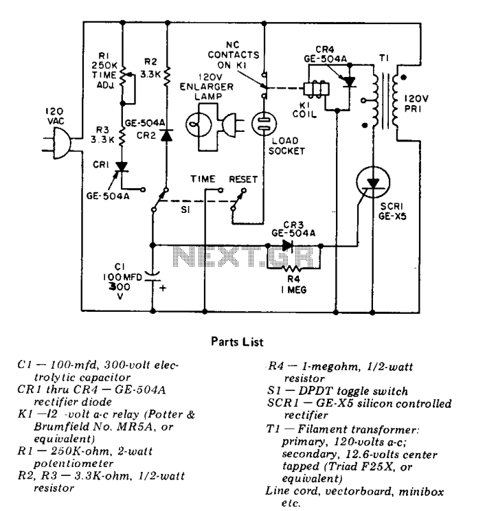
This precision solid-state time delay circuit features both delayed off and delayed on switch functions, which can be interchanged by simply swapping the relay contacts. The described time delay circuit is designed to provide precise control over the timing of...
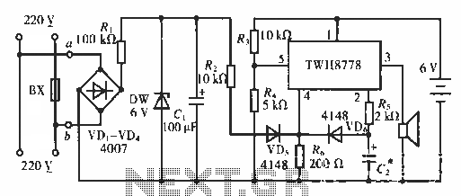
The circuit functions as an AC blown fuse alarm. When the fuse (BX) is intact, 220 V AC voltage passes through a bridge rectifier composed of diodes VD1 to VD4. Resistor R1 limits the current, and the output is...
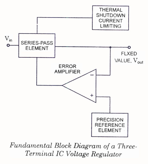
IC Voltage Regulators - Circuit diagram and block diagram of linear, fixed, adjustable (positive and negative), and switching voltage regulators. IC voltage regulators are essential components in electronic circuits, providing stable output voltages from a varying input voltage source. They...

The circuit depicted in Figure 13-4 utilizes triode control. Two transistors, VTi and VTz, are coupled via a capacitor (C) to alternately turn on and off, producing a flashing light effect. The flash frequency is influenced by the capacitance...
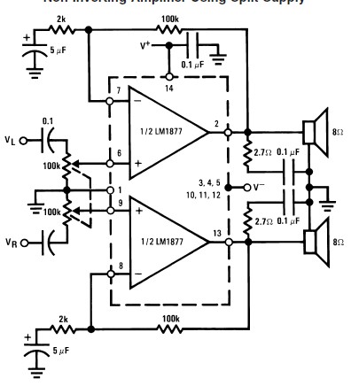
This audio amplifier circuit is designed to deliver 2W per channel continuously into 8-ohm loads. The LM1877 is engineered to function with a minimal number of external components while still offering flexibility for applications in stereo phonographs, tape recorders,...