
IC Voltage Regulators-withCircuit - Design & Theory

IC voltage regulators are essential components in electronic circuits, providing stable output voltages from a varying input voltage source. They can be categorized into several types, including linear regulators, fixed regulators, adjustable regulators, and switching regulators.
Linear voltage regulators maintain a constant output voltage by using a feedback mechanism to adjust the resistance within the circuit. The block diagram typically illustrates the input voltage, the regulator, and the output voltage, along with feedback paths. Fixed voltage regulators provide a predetermined output voltage, while adjustable voltage regulators allow for output voltage customization through external resistors.
Switching voltage regulators, on the other hand, utilize a different principle. They convert the input voltage to a high-frequency square wave and then use inductors, capacitors, and diodes to filter and smooth the output. This method is more efficient than linear regulation, especially for applications requiring significant power conversion.
The circuit diagrams for these regulators vary based on their design and application. For linear regulators, the schematic often includes a pass transistor, input and output capacitors, and a feedback network. Fixed regulators feature a simpler design, while adjustable regulators incorporate additional components for voltage setting. Switching regulators are more complex, showcasing components like inductors, diodes, and control ICs.
Understanding the differences and applications of these voltage regulators is crucial for designing reliable and efficient electronic systems. Each type serves specific needs, whether it be low dropout voltage in linear regulators or high efficiency in switching regulators, making them indispensable in modern electronics.IC Voltage Regulators -Circuit diagram & Block diagram of Linear,Fixed, Adjustable (positive & negative) & Switching voltage regulators.. 🔗 External reference
Related Circuits
This constant current constant voltage switched-mode power supply (SMPS) is designed for efficient battery charging. The circuit outputs a constant voltage of 7.2V and a constant current of 600mA. The operation mechanism is straightforward: when the load impedance is...
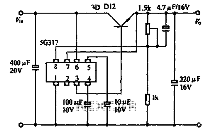
The 5G317 is an integrated voltage regulator circuit used in wiring applications for televisions. The maximum input voltage for the 5G317 should be less than 25V, while the output voltage ranges from 10V to 18V. The maximum output current,...
Flyback transformers are commonly used in television sets and can generate up to 50,000 volts, which is sufficient to lift a 350-pound individual and throw them back 10 to 20 feet, potentially causing fatal injuries. The components are sensitive...
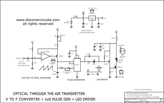
This circuit receives the signal from the amplifier and emits powerful 1μs infrared light pulses from a low-cost LED, which are frequency modulated by the audio information. The 10kHz center frequency of the pulse stream is sufficiently low, allowing...
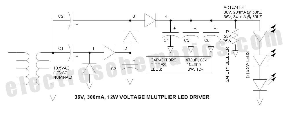
This power supply circuit is designed around a standard 12VAC landscape lighting transformer. The availability and selection of transformers have long posed challenges for experimenters, often leading them to use potentially hazardous off-line capacitor-limited power supplies. However, the widely...
High-voltage power supply circuit for fluorescent light power supply. Refer to that page for an explanation of the related circuit diagram. The high-voltage power supply circuit designed for fluorescent lights typically consists of several key components that work together to...