
Tesla Coil Powerful Radio Transmitter with A Lousy Antenna

The Tesla Coil is an electrical resonant transformer circuit that is designed to produce high-voltage, low-current, high-frequency alternating current electricity. It consists of two main components: a primary coil and a secondary coil, which are coupled inductively. The primary coil is energized by a power source, typically a capacitor bank, which discharges through the coil, creating a magnetic field. This magnetic field induces a current in the secondary coil, where the voltage is stepped up significantly due to the turns ratio between the primary and secondary coils.
The secondary coil, which acts as a quarter-wave antenna, resonates at a specific frequency determined by its physical dimensions and the surrounding environment. This resonance allows the Tesla Coil to produce high-frequency oscillations, resulting in the generation of high-voltage discharges. The efficiency of the antenna, however, is limited, leading to a significant amount of energy being lost as radiation rather than being effectively transmitted.
In practical applications, Tesla Coils are often used for demonstrations in educational settings to illustrate principles of electromagnetic fields and resonance. They can also be utilized in various experimental setups, including wireless power transmission and high-voltage experiments. The design of a Tesla Coil requires careful consideration of components such as capacitors, spark gaps, and transformers to ensure safe operation and optimal performance.
Safety precautions are paramount when working with Tesla Coils due to the high voltages involved, which can pose serious risks. Proper grounding, insulation, and protective equipment are essential to mitigate hazards associated with electric shock and arc flash.I have tried to figure out what exactly a Tesla Coil was for years. I finally occurred to me that the best way to think of a Tesla Coil was as a very high power rf transmitter simply with a terrible antenna. The secondary is really just an ultra shortened 1/4 wave antenna. 🔗 External reference
Related Circuits
Its frequency depends on the capacitance of the vary cap diode. The center frequency is changed by varying the biasing voltage of the vary cap through the 47K pot. You can use a 75cm telescopic antenna or simply a...
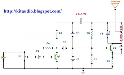
The circuit is a radio frequency (RF) oscillator functioning at approximately 100 MHz. Audio signals captured and amplified by an electret microphone are routed to an audio amplifier stage constructed around the first transistor. The output from the collector...
This circuit diagram is part of an RF circuit. It features an FM transmitter circuit diagram using the BH1417 integrated circuit from RHOM, which incorporates multiple functionalities in a compact design. The IC includes pre-emphasis and a limiter to...
In this circuit, a 74HC14 hex Schmitt trigger inverter is used as a square wave oscillator to drive a small signal transistor in a class C amplifier configuration. The oscillator frequency can be either fixed by a crystal or...
This project is straightforward to construct and will transmit high-quality sound within the FM band (88-108 MHz). An important component is that the... This project involves the design and construction of a simple FM transmitter capable of broadcasting audio signals...
This metal detector schematic circuit is based on a transistor radio as a detector. This metal detector is entirely different from other metal detectors because this circuit does not have a speaker. With the radio tuned to a weak...