
AM Broadcast Transmitter schematic

The circuit utilizes a 74HC14 hex Schmitt trigger inverter, which is a CMOS device known for its ability to convert slow or noisy signals into clean digital signals. In this application, it functions as a square wave oscillator, generating a continuous waveform that drives a small signal transistor configured in a class C amplifier arrangement. The oscillator's frequency can be set either by a crystal oscillator for stability or by using a variable frequency oscillator (VFO) setup, which includes a 100pF capacitor and a resistor network, allowing for frequency adjustments based on user requirements.
The amplitude modulation is achieved through a secondary transistor, which modulates the DC voltage supplied to the output stage. This modulation allows for varying the amplitude of the output signal while maintaining a constant frequency. The output stage is designed to operate with a bias point set to approximately half of the supply voltage (6 volts), ensuring that the amplifier operates efficiently and delivers the desired output without modulation.
To match the output stage to the antenna, a variable capacitor ranging from 30 to 365 pF is employed. This tuning capacitor allows for impedance matching, optimizing the power transfer to the antenna. When properly tuned, the output stage can deliver approximately 20 mA of current through the antenna lead, particularly effective at frequencies near the upper end of the broadcast band, around 1.6 MHz.
The antenna used in this circuit is a dipole antenna approximately 9.8 feet in length, which is compliant with FCC regulations for low-power transmission. The antenna's design and dimensions are critical for ensuring efficient radiation of the signal. The circuit's output power is estimated to be around 40 microwatts, with a range of approximately 80 feet under optimal conditions.
A 'grain of wheat' lamp serves as a visual indicator of the antenna current, helping to achieve the best tuning settings. The inductor used in the circuit is designed with a specific inductance of 140 µH, created by winding 120 turns of #28 copper wire around a 2-inch length of PVC pipe, further contributing to the circuit's performance.
Radiated power can be mathematically approximated using the antenna's radiation resistance and the square of the antenna current. For a dipole antenna with a length less than 1/4 wavelength, the radiation resistance can be calculated, allowing for precise estimation of the radiated power, which is crucial for understanding the circuit's transmission capabilities.In this circuit, a 74HC14 hex Schmitt trigger inverter is used as a square wave oscillator to drive a small signal transistor in a class C amplifier configuration. The oscillator frequency can be either fixed by a crystal or made adjustable (VFO) with a capacitor/resistor combination.
A 100pF capacitor is used in place of the crystal for VFO operation. Amplitude modulation is accomplished with a second transistor that controls the DC voltage to the output stage. The modulator stage is biased so that half the supply voltage or 6 volts is applied to the output stage with no modulation.
The output stage is tuned and matched to the antenna with a standard variable 30-365 pF capacitor. Approximately 20 milliamps of current will flow in the antenna lead (at frequencies near the top of the band) when the output stage is optimally tuned to the oscillator frequency. A small 'grain of wheat' lamp is used to indicate antenna current and optimum settings. The 140 uH inductor was made using a 2 inch length of 7/8 inch (OD) PVC pipe wound with 120 turns of #28 copper wire.
Best performance is obtained near the high end of the broadcast band (1.6 MHz) since the antenna length is only a very small fraction of a wavelength. Input power to the amplifier is less than 100 milliwatts and antenna length is 3 meters or less which complies with FCC rules.
Output power is somewhere in the 40 microwatt range and the signal can be heard approximately 80 feet. Radiated power output can be approximated by working out the antenna radiation resistance and multiplying by the antenna current squared.
The radiation resistance for a dipole antenna less than 1/4 wavelength is R = 80*[(pi)^2]*[(Length/wavelength)^2]*(a factor depending on the form of the current distribution) The factor depending on the current distribution turns out to be [(average current along the rod)/(feed current)]^2 for short rods, which is 1/4 for a linearly-tapered current distribution falling to zero at the ends. Even if the rods are capped with plates, this factor cannot be larger than 1. Substituting values for a 9.8 foot dipole at a frequency of 1.6 MHz we get R= 790*.000354*.25 = .07 Ohms.
And the resistance will be only half as much for a monopole or 0.035 Ohms. Radiated power at 20 milliamps works out to about I^2 * R = 14 microwatts. 🔗 External reference
Related Circuits
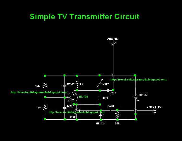
Many individuals inquire about TV transmitters. This document provides a useful circuit diagram that enables signal transmission over distances of 75 to 100 meters. The circuit diagram is not original; it was provided by a friend. Contributions of circuit...
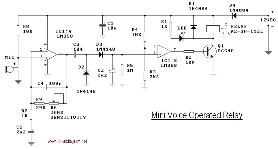
This mini-VOX voice-operated relay is based on a circuit published in Silicon Chip, September 1994, page 31. The off-delay time can be adjusted by varying resistors R3 and R4. Reducing R3 will result in a longer release time. It...
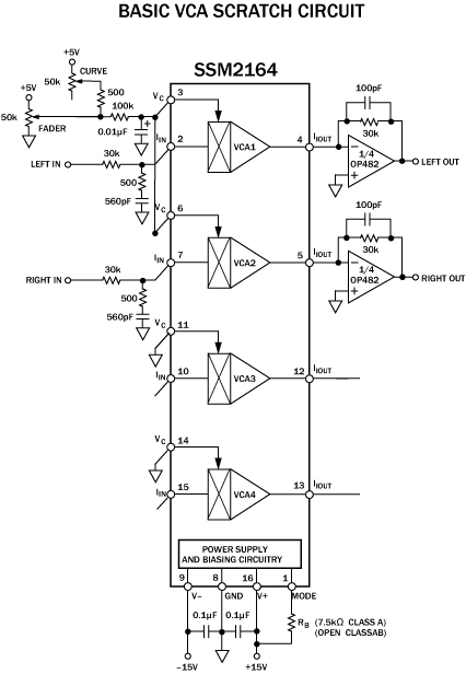
The cut on a fader is fundamentally different from a transform. It is not an instantaneous on/off switch; rather, it features a gradual slope that can range anywhere from a few hundred microseconds to tens of milliseconds. This duration...
This page contains some information on circuits which can be used for triggering stroboscopes from external circuits. The circuits here are designed to be integrated into stroboscope circuits so that they can be triggered using an external trigger pulse....
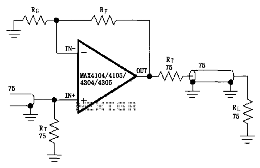
The circuit illustrated in the figure features a MAX4104/4105/4304/4305 video cable driver amplifier. This circuit is designed for use with coaxial transmission lines, optimizing the amplification of video signals to minimize reflections and maximize power transfer. The output impedance...
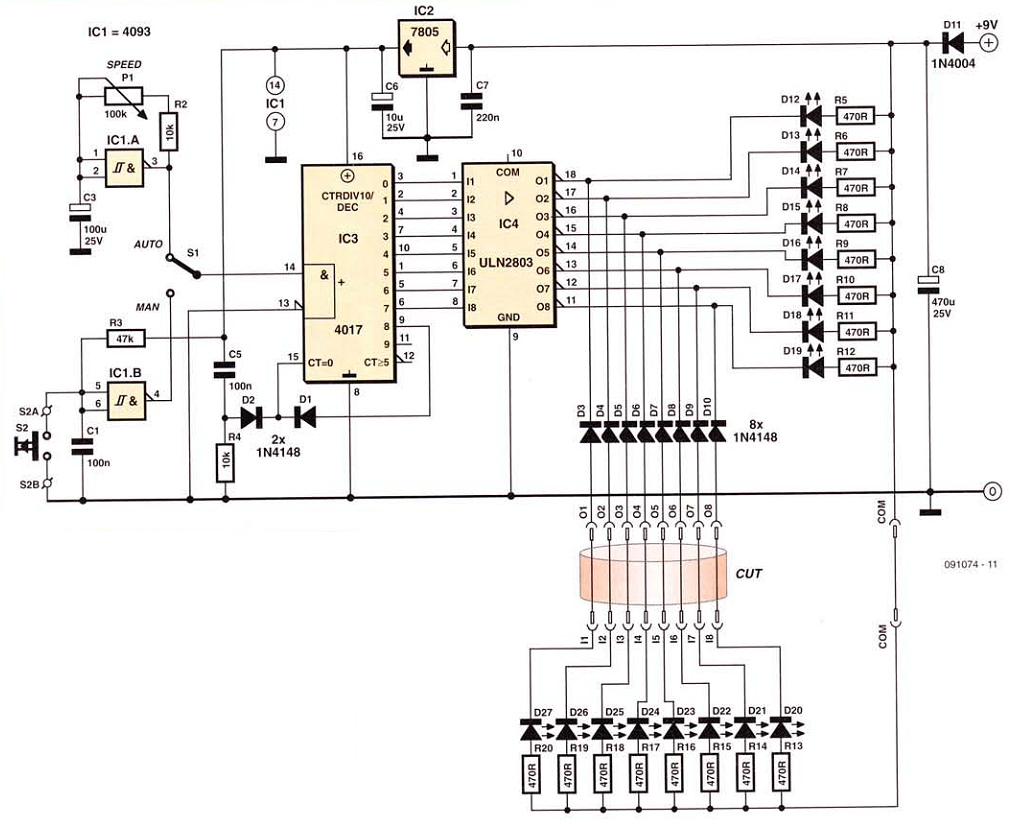
This network wiring tester consists of two components: a transmitter unit, which is powered and installed at the network's starting point, and a passive receiver unit that can be moved from socket to socket. Both units contain eight LEDs,...