
Tesla's Energy Reciever
But, on his 76th birthday, at the ritual press conference, Tesla (who was without the financial wherewithal to patent but went on inventing in his head) announced a "cosmic-ray motor." When asked if it was more powerful than the Crooke's radiometer, he answered, "thousands of times more powerful."
How it works
From the electric Potential that exists between the elevated plate (plus) and the ground (minus), energy builds in the capacitor, and, after "a suitable time interval," the accumulated energy will "manifest itself in a powerful discharge" which can do work. The capacitor, says Tesla, should be "of considerable electrostatic capacity," and its dielectric made of "the best quality mica,' for it has to withstand potentials that could rupture a weaker dielectric.
Tesla gives various options for the switching device. One is a rotary switch that resembles a Tesla circuit controller. Another is an electrostatic device consisting of two very light, membranous conductors suspended in a vacuum. These sense the energy build-up in the capacitor, one going positive, the other negative, and, at a certain charge level, are attracted, touch, and thus fire the capacitor. Tesla also mentions another switching device consisting of a minute air gap or weak dielectric film which breaks down suddenly when a certain potential is reached.
The above is about all the technical detail you get in the patent. Although I've seen a few cursory references to Tesla's invention in my sampling of the literature of free-energy, I am not aware of any attempts to verify it experimentally.
The Tesla free-energy receiver operates on the principles of electrostatics and radiant energy collection. The core component is a capacitor designed to accumulate electric charge through the influence of ambient radiant energy, including cosmic rays and solar radiation. The elevated plate of the capacitor serves as the positive terminal, while the ground acts as a negative terminal, creating a potential difference that facilitates energy storage.
The capacitor must possess significant electrostatic capacity, with a dielectric material of high quality, such as mica, to withstand the high voltage levels expected during operation. The dielectric is crucial as it prevents dielectric breakdown, which could lead to catastrophic failure of the capacitor.
For the energy discharge mechanism, Tesla proposed several switching devices. The rotary switch operates similarly to traditional circuit controllers, allowing for controlled energy release. The electrostatic switch, comprising lightweight conductors in a vacuum, relies on the principles of electrostatic attraction. As the capacitor charges, one conductor becomes positively charged while the other becomes negatively charged. Upon reaching a predetermined voltage, the two conductors attract, making contact and triggering the capacitor's discharge.
Another switching option involves a dielectric film with a specific breakdown voltage. When the voltage across this film exceeds its threshold, it rapidly fails, allowing the stored energy in the capacitor to be released in a sudden discharge. This rapid release can drive mechanical loads or power electrical devices, demonstrating the potential of Tesla's free-energy receiver.
The schematic would include the capacitor connected to the elevated plate and ground, with the various switching devices illustrated to show their configurations. Overall, Tesla’s design reflects a pioneering approach to harnessing energy from the environment, emphasizing the need for high-quality materials and innovative switching mechanisms to effectively utilize radiant energy.Tesla's free-energy receiver was patented in 1901 as An Apparatus for the Utilization of Radiant Energy. The patent refers to "the Sun, as well as other sources of radiant energy, like cosmic rays." That the device works at night is explained in terms of the night-time availability of cosmic rays.
Tesla also refers to the ground as "a vast reservoir of negative electricity." Tesla was fascinated by radiant energy and its free-energy possibilities. He called the Crooke's radiometer (a device which has vanes that spin in a vacuum when exposed to radiant energy) "a beautiful invention." He believed that it would become possible to harness energy directly by "connecting to the very wheelwork of nature." His free-energy receiver is as close as he ever came to such a device in his patented work. But, on his 76th birthday, at the ritual press conference, Tesla (who was without the financial wherewithal to patent but went on inventing in his head) announced a "cosmic-ray motor." When asked if it was more powerful than the Crooke's radiometer, he answered, "thousands of times more powerful." How it works From the electric Potential that exists between the elevated plate (plus) and the ground (minus), energy builds in the capacitor, and, after "a suitable time interval," the accumulated energy will "manifest itself in a powerful discharge" which can do work.
The capacitor, says Tesla, should be "of considerable electrostatic capacity," and its dielectric made of "the best quality mica,' for it has to withstand potentials that could rupture a weaker dielectric. Tesla gives various options for the switching device. One is a rotary switch that resembles a Tesla circuit controller. Another is an electrostatic device consisting of two very light, membranous conductors suspended in a vacuum.
These sense the energy build-up in the capacitor, one going positive, the other negative, and, at a certain charge level, are attracted, touch, and thus fire the capacitor. Tesla also mentions another switching device consisting of a minute air gap or weak dielectric film which breaks down suddenly when a certain potential is reached.
The above is about all the technical detail you get in the patent. Although I've seen a few cursory references to Tesla's invention in my sampling of the literature of free-energy, I am not aware of any attempts to verify it experimentally. 🔗 External reference
Related Circuits
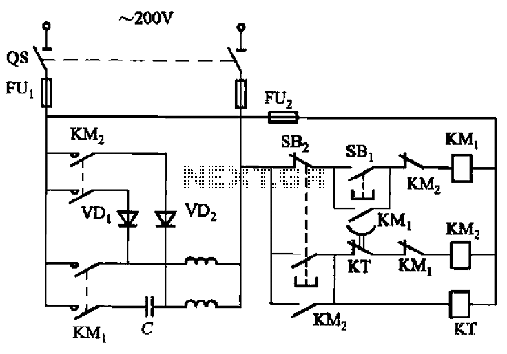
The circuit depicted in Figure 3-150 involves a contactor (KM1) that releases when the system is shut down. The contactor KM2 is energized, allowing a 220V AC power supply to flow through diodes VD1 and VD2, which serve as...

The Kapanadze device operates on the same principle as the oscillator-shuttle circuit discovered by Tesla over a century ago, and similarly aligns with concepts described by Bearden three decades ago regarding electrical free energy. This prior art may render...
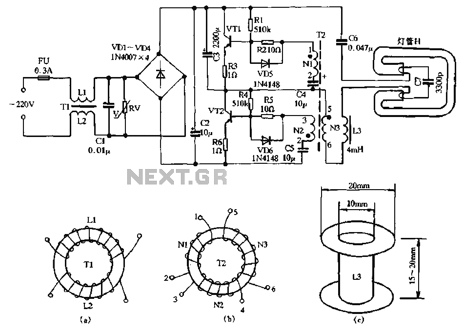
The circuit diagram illustrates a dedicated electronic ballast circuit for a 16W2D single-ended energy-saving lamp. The RFI filter circuit consists of components such as zinc oxide varistors for protection, bridge rectifiers, a high-frequency oscillator, and an LC series output...
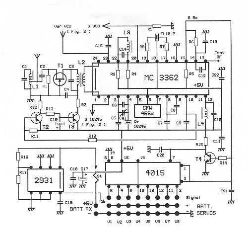
This receptor is born of our annoyance against the irritating problem of Quartz: With the RX21, completed research of cut crystal for your personal rating, you have with him, access to ALL band frequencies, in steps of 5 kHz!...
Convert the smart cards into manual push buttons to control energy consumption, alleviating the consumer's concern about sourcing smart cards, especially given the limited supply in the area. The proposed modification involves replacing the current smart card system with...
The 22-turn coil is positioned above the 84-turn coil. Connecting this coil significantly impacts performance. Testing with a 1 kW heater yielded better results; however, prolonged use may lead to failure. The heater's wire typically does not glow as...