
Energy-saving lamp electronic ballast circuit

The electronic ballast circuit for the 16W2D single-ended energy-saving lamp is designed to provide efficient operation while ensuring protection against electrical anomalies. The inclusion of the RFI filter circuit is crucial for minimizing electromagnetic interference, which can adversely affect the performance of the lamp and surrounding electronic devices. The zinc oxide varistors serve as a vital safety feature, providing rapid response to voltage spikes or phase errors, thereby preventing damage to both the ballast and the lamp.
The bridge rectifier, constructed from diodes VD1 to VD4, is essential for converting the alternating current (AC) input into direct current (DC), which is necessary for the operation of the electronic components in the circuit. The filter capacitor C2 smooths out the rectified voltage, ensuring a stable DC supply for the oscillator.
The high-frequency oscillator is the heart of the circuit, responsible for generating the necessary frequency to ignite the lamp. The transformer coupling in the oscillator allows for efficient energy transfer between the transistors VT1 and VT2. The design ensures that as one transistor turns on, it induces the other to turn on in a controlled manner, creating a self-sustaining oscillation. This oscillation is critical for generating the high-frequency signals required for lamp ignition.
The series resonance created by choke coil L3 and capacitor C7 enhances the voltage across C7, facilitating the initial ignition of the lamp. Once the lamp is lit, the circuit adjusts to maintain normal operation, demonstrating the adaptability of the electronic ballast in response to varying load conditions. The careful selection of component values in the LC series circuit allows for optimal performance, ensuring that the lamp operates efficiently and reliably throughout its lifespan.Start within 16W2D single ended energy saving lamp dedicated electronic ballast circuit shown in Figure, RFI filter circuit consists of 1-60 wave, a zinc oxide varistor protection, bridge rectifiers, high-frequency oscillator, LC series part of the output stage and so on. RFI filter inductor Ll, L2 and capacitor Cl form, while the power factor of the circuit capacitor Cl also have some corrective action.
RV zinc oxide varistors, when the grid voltage increases or accidental wrong phase can be quickly turned on so fast fuse FU fuse to protect the electronic ballast and the lamp from damage. Bridge rectifier circuit composed by the VDI ~ VD4, filter capacitor C2 and then dried. High frequency oscillator using transformer coupling of oscillating circuit, in just an instant power, although the same VTI and VT2 loop circuit parameters, but since components of the discrete nature, which is bound to make a priority transistor is turned on, and then rely on coupling transformer T2, so that the other transistor is turned on and the pilot through a transistor is turned on by the state jump into the oFF-state.
T2 flux through positive and negative cyclical changes, so VTI, VT2 turns saturated conduction and off, quickly establish oscillation. Once excited oscillation circuit, high-frequency signal number is through a series circuit of a choke coil L3 and capacitor C7 and other components, causing series resonance, so in the C7 generated across a high resonant voltage to ignite the lamp H one-time activation.
Once the lamp is ignited, Lc series circuit detuning, as long as the circuit element parameters by selecting the appropriate number of lights can work in a normal nominal state.
Related Circuits
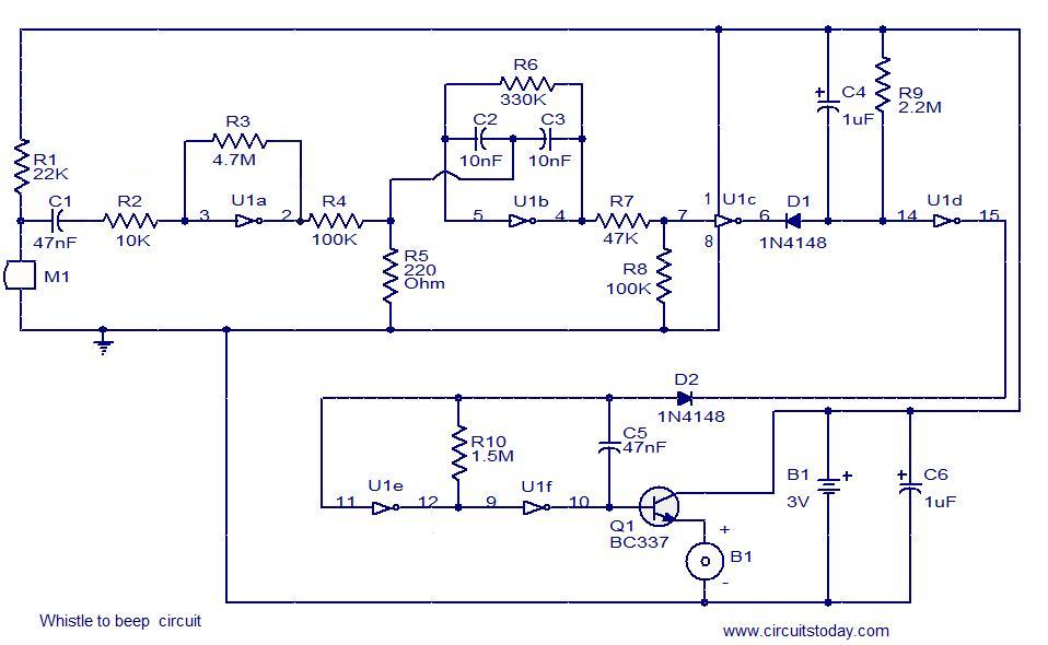
This simple circuit produces a beeping sound that lasts for approximately 3 seconds whenever a whistle is made. The CMOS Hex inverter CD4049 serves as the core component of this circuit. Among the six inverters in the CD4049, U1a...
This miniature audio amplifier provides an output of up to 250mW and can function as a final stage audio amplifier for radio sets. The schematic is straightforward, featuring one BC transistor. The described miniature audio amplifier is designed for efficient...
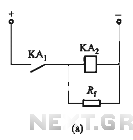
The circuit depicted in Figure 6-24 includes a relay coil with both ends connected in parallel to either a resistor Rf or an auxiliary diode VD. This configuration is equivalent to providing power after a short circuit, which increases...
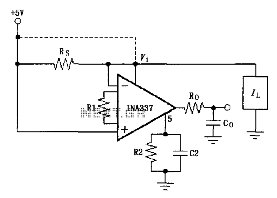
The INA337 circuit, as illustrated, is part of a load current measuring shunt circuit. It generates a voltage drop across the sampling resistor Rs, which is connected in series between the power source and the load. The load current...
The project involves installing LED strips in a car's tail lamps to replace conventional bulbs. The required lengths for the LED strips are 16 inches, 15 inches, and 14 inches to fit properly within the housings. The selected LED...
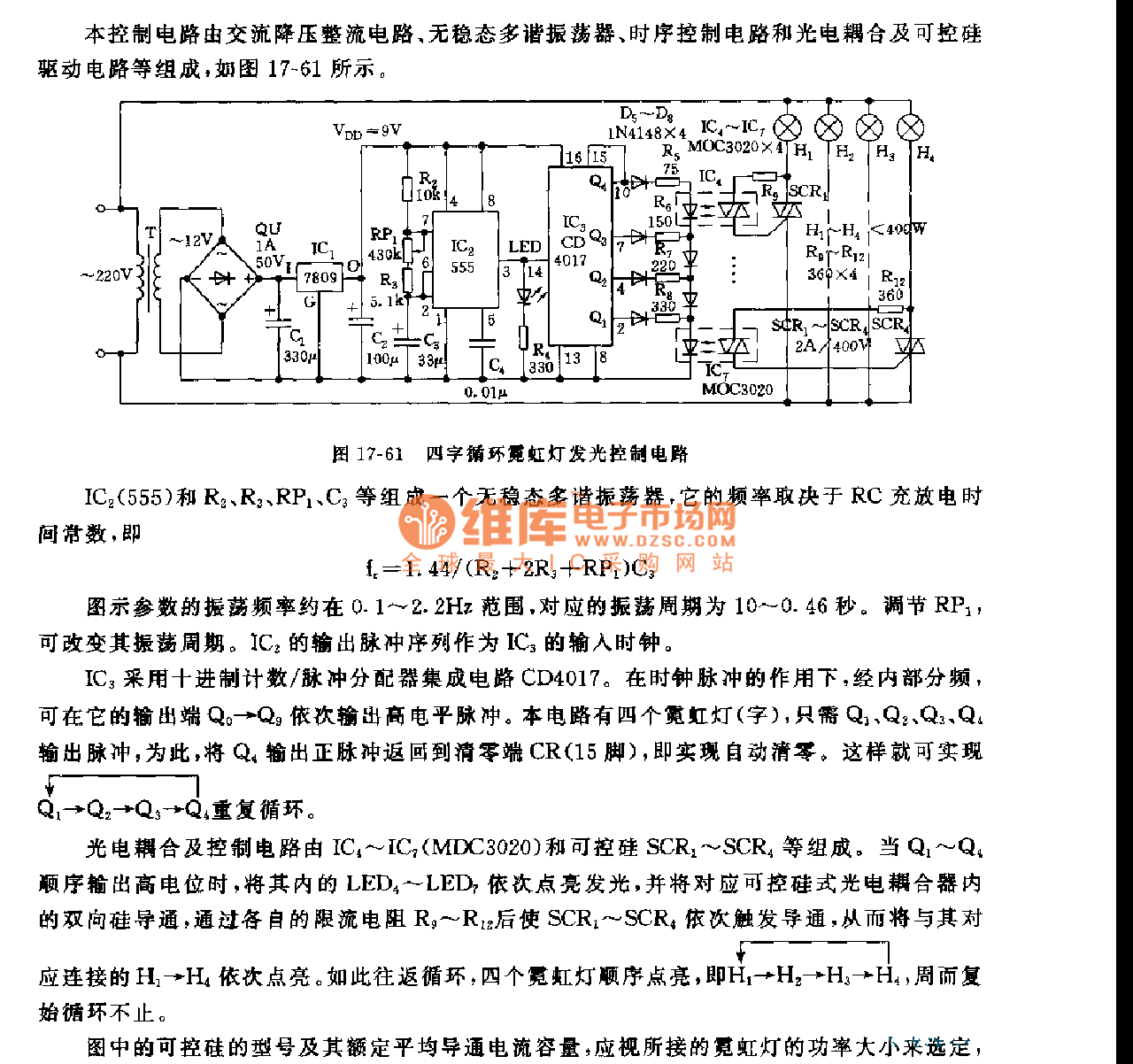
This control circuit consists of an AC step-down rectifier circuit, an astable multivibrator, a timing control circuit, an optocoupler circuit, and an SCR driving circuit, as illustrated in Figure 17-61. The astable multivibrator is formed using IC2 (555), resistors...