
Test Beeper For Your Stereo

The test beeper circuit utilizes a Wien bridge oscillator, which is renowned for its ability to produce stable sine wave signals. The oscillator comprises resistors and capacitors arranged in a specific configuration to establish the desired frequency of oscillation. In this case, the frequency of 1,000 Hz is achieved through precise selection of resistor and capacitor values.
The Wien bridge oscillator consists of two arms of resistors and two arms of capacitors. The resistive elements set the gain of the circuit, while the capacitive elements determine the frequency. The feedback loop within the oscillator ensures that the output maintains a sinusoidal waveform. To stabilize the oscillation amplitude, a thermistor or light-dependent resistor (LDR) is often used, which adjusts the gain dynamically based on the output signal level.
The output of the oscillator is typically connected to a buffer amplifier to drive the load without affecting the oscillator's performance. This buffered output can be used to test audio amplifiers, speakers, or other audio equipment, providing a clean reference signal for analysis.
In summary, the test beeper circuit serves as a reliable tool for generating a 1,000 Hz sine wave, facilitating the testing and evaluation of audio amplifiers and other related devices.The test beeper generates a sinusoidal signal with a frequency of 1,000 Hz, a common test frequency for audio amplifiers. It consists of a classical Wien-.. 🔗 External reference
Related Circuits
A simple and easy telephone line tester circuit that can be used for testing telephone lines. The telephone line tester circuit is designed to verify the functionality and integrity of telephone lines. It typically comprises a few essential components, including...
To build a stepper motor tester, the circuit includes two sets of drivers that support both unipolar and bipolar stepper motors. The control circuit and driver circuit are powered by separate supplies, allowing compatibility with a wider range of...
A low resistance (0.25 - 4 ohm) continuity tester for checking soldered joints and connections. This simple circuit uses a 741 op-amp in differential mode as a continuity tester. The voltage difference between the non-inverting and inverting inputs is...
The TS2418 is a monolithic integrated circuit telephone tone ringer that utilizes a bridge diode. When paired with an appropriate transducer, it serves as a replacement for traditional electromechanical bells. This device is compatible with either a piezo transducer...
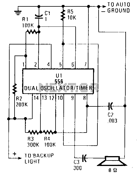
When the vehicle is placed in reverse, the circuit emits a loud beep at a frequency of approximately one beep per second (1Hz). Half of the U1 component, a 556 dual oscillator/timer, functions as a slow-pulse oscillator with a...
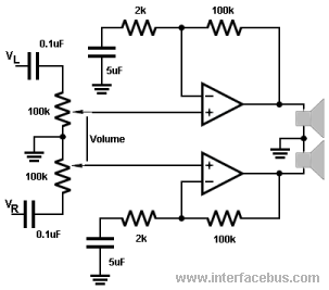
The 100k potentiometers adjust the voltage levels reaching the operational amplifiers (Op Amps). A dual ganged 100K-Ohm audio-taper potentiometer is preferred over a linear taper potentiometer. In some instances, this component may be referred to as a ganged stereo...