
Test Gear Circuits

In addition, the circuit can be constructed using two gates from a CMOS 4011 NAND chip to create a simple square wave oscillator. Alternatively, a CMOS 4001 chip or a TTL equivalent can be employed. The mark-space ratio in this circuit can be independently controlled by adjusting resistor values. The rise and fall times of the output pulses depend on the operating voltage and type of IC but are generally in the order of tens of nanoseconds. A logic probe designed with a single CMOS IC indicates three logic conditions: High, Low, and Pulsing. If the probe input is in a high impedance state (neither high nor low), no LEDs will illuminate. Power for the logic probe is sourced from the logic circuit under test, allowing testing of voltages ranging from 3 to 15 volts. IC1a is configured as a buffer with a difference; under no input conditions (i.e., when the probe is not connected), the gate oscillates due to feedback from a 2.2M resistor. The output voltage at IC1a is approximately half the supply voltage. The high and low logic indicator LEDs are connected to a potential divider formed by two 1k resistors, maintaining half the supply voltage at their junction; hence, no LEDs will light when in high impedance. A high or low logic condition causes IC1a to settle in a permanent state, indicated by either the high or low LED illuminating. A fast oscillator or clock signal will cause both high and low LEDs to light, albeit dimly. To address this, IC1b and IC1c are included, forming a monostable oscillator with a time constant determined by a 100nF capacitor.Using a single 555 Timer IC and a small transformer to generate a high voltage, this circuit will test zener diodes of voltage ratings up to 50VDC. The 555 timer is used in the astable mode, the output at pin3 drives a small audio transformer such as the LT700.
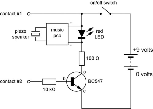
This has a primary impedance of 1K and a secondary impedance of 8 ohms. Used in reverse the unloaded ac voltage is around 120volts ac. This is rectified by the 1N4004 diode and smoothed by the 2. 2u capacitor which MUST be rated at 150 VDC. The zener under test is measured with a multimeter set to DC volts as shown. The load current switch enables the zener to be tested at 1 or 2mA DC. The rectified DC load, but a good zener should maintain the reading on the volt meter. This circuit is the result of Andy Collinson research. He has used a photodiode, SFH2030 as an infra red sensor. A MOSFET opamp, CA3140 is used in the differential mode to amplify the pulses of current from the photodiode. LED1 is an ordinary coloured led which will light when IR radiation is being received. The output of the opamp, pin 6 may be connected to a multimeter set to read DC volts. Infra red remote control strengths can be compared by the meter reading, the higher the reading, the stronger the infra red light.
He aimed different remote control at the sensor from about 1 meter away when comparing results. For every microamp of current through the photodiode, about 1 volt is produced at the output. A 741 or LF351 will not work in this circuit. Although he has used a 12 volt power supply, a 9 volt battery will also work here. Using a single 555 Timer IC and a small transformer to generate a high voltage, this circuit will test zener diodes of voltage ratings up to 50VDC. The 555 timer is used in the astable mode, the output at pin3 drives a small audio transformer such as the LT700.
This has a primary impedance of 1K and a secondary impedance of 8 ohms. Used in reverse the unloaded ac voltage is around 120volts ac. This is rectified by the 1N4004 diode and smoothed by the 2. 2u capacitor which MUST be rated at 150 VDC. The zener under test is measured with a multimeter set to DC volts as shown. The load current switch enables the zener to be tested at 1 or 2mA DC. The rectified DC load, but a good zener should maintain the reading on the volt meter. Using two gates from a CMOS 4011 NAND chip, a simple Squarewave oscillator can br made. Alternatively a CMOS 4001 chip can also be used, or a TTL equivalent. In this circuit the mark space ratio can also be independently controlled by varying the value of the resistors. The rise and fall times of the output pulses depend on the operating voltage of the IC and type of IC, but will be typically in the order on tens of nanoseconds.
This logic probe uses a single CMOS IC and shows three logic conditions, High, Low and Pulsing. In addition if the probe input is neither hi or low (the high impedance state of tri-output logic ic`s) then no LED`s will light. Power from the logic probe is taken from the logic circuit under test; using a CMOS IC enables logic circuits to be tested using voltages from 3 to 15 volts.
IC1a is arranged as a buffer with a difference. Under no input, i. e. probe not connected to circuit the gate will oscillate due to feedback from the 2M2 resistor. Output voltage at IC1a is approximately half supply voltage. The Hi and Lo logic indicator LED`s are also connected to a potential divider consisting of the two 1k resistors. Voltage at the junction is half supply voltage hence with no input, or high impedance no LED`s will light.
A Hi or Lo logic condition will cause IC1a to rest in a permanent state indicated by either the Hi or Lo LED illuminating. With a fast oscillator or clock signal both Hi and Lo LED`s will light but will be quite dim. This is the reason for IC1b and IC1c. These two gates form a monostable oscillator, time constant determined by the 100n capacitor and 🔗 External reference
Related Circuits
A continuity tester is useful for verifying that there is a conductive path between two points. This circuit offers the advantage of being highly sensitive, providing both visual and audible indications of continuity. An audible tester is particularly beneficial...
For the shorter wavelength VHF and UHF bands, it is more practical to construct complex antennas such as a single-band Slim Jim or Yagis. Various projects include creating an electronic unit, as it is necessary for the Intermediate Level...
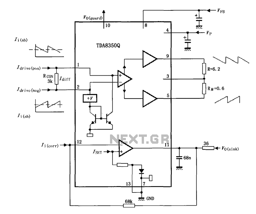
The TDA8350Q test circuit includes a push-pull amplifier configuration where the output terminal resistor serves as a dummy load for testing an alternative deflection coil. The TDA8350Q is a high-performance integrated circuit designed for use in television and display systems....
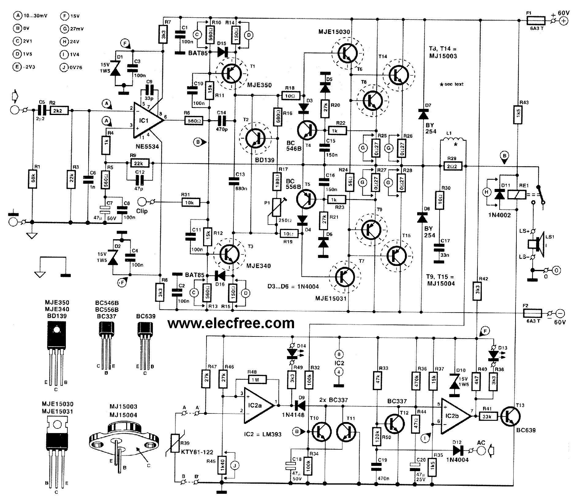
This circuit is designed for friends who are interested in high-power amplifier circuits. It can deliver approximately 300 Watts RMS and operates as an OCL (Output Capacitor-Less) Class AB amplifier, providing high sound power while systematically protecting the loudspeaker...
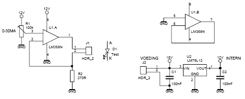
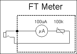
This led tester uses a power switched op-amp. The control range is about 0-30mA. Thus, all test and standard LEDs, the voltage across the LED to read. The power supply is an example lab power supply at least 15V,...
This is a luminous flux test circuit that utilizes optical resistors. In the circuit, the optical resistor RG forms a bridge with resistors RP1, RP2, R1, and R2. RP1 is employed to balance the bridge, while RP2 is used...