
The luminous flux test circuit with optical resistors

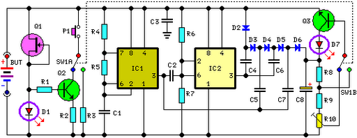
The luminous flux test circuit is designed to measure light intensity using a configuration of optical resistors, which change their resistance based on the amount of light exposure. The core of this circuit is a Wheatstone bridge formed by RG, RP1, RP2, R1, and R2. The optical resistor RG responds to light levels, altering the resistance and thus influencing the balance of the bridge.
Resistor RP1 serves a critical role in fine-tuning the bridge balance. By adjusting RP1, the user can achieve equal voltage levels at nodes a and c, which is essential for accurate measurements. The second variable resistor, RP2, is responsible for adjusting the sensitivity of the entire circuit, allowing the user to calibrate the response to varying light conditions.
When the circuit is balanced—meaning the voltages at points a and c are equal—the output voltages VT1 and VT2 drop to zero. This condition indicates that the thyristor in the VSI section of the circuit is no longer conducting, effectively turning it off. The design ensures that the circuit can operate effectively under different lighting conditions by providing a means to adjust both the balance and sensitivity, making it suitable for applications requiring precise luminous flux measurements.
Overall, this luminous flux test circuit exemplifies the use of optical resistors in a bridge configuration to achieve accurate light intensity readings, with adjustable parameters for fine-tuning performance.This is a luminous flux test circuit with optical resistors. In the circuit, the optical resistor RG forms a bridge with RP1,RP2,R1 and R2; RP1 is used to adjust the balance of the bridge; RP2 is used to adjust the sensitivity of the circuit. If we adjust RP1 to make the voltages on a and c are equal, then VTl and VT2 stop, and the thyristor of VSI is off.
I.. 🔗 External reference
Related Circuits
This indicator shows through a dual-LED see if a fuse is intact. The module is designed for 230 V AC. The green LED illuminates when the fuse is still good, the red lights when the fuse is broken. Perhaps...
This circuit performs a rapid battery test without requiring a power supply or costly moving-coil voltmeters. It offers two testing ranges: when switch SW1 is positioned as indicated in the circuit diagram, the device can test batteries ranging from...

The circuit illustrated in Figure 4 is an AC timing circuit designed to operate for 4 hours. It utilizes the BH4024, a 7-stage serial binary counter/divider, in conjunction with a 555 timer circuit. The circuit is activated by a...

This circuit adds a power-down function to analog I/O ports, such as the AD7769 and AD7774. Additionally, the diodes typically required to protect the devices against power-supply mis-sequencing can be eliminated. In this design, MOSFETs Q1 and Q2 switch...
Electronics tutorial about the monostable multivibrator circuit, also known as a one-shot monostable multivibrator, used as a pulse generator circuit. The monostable multivibrator is a crucial component in electronic circuits, functioning as a pulse generator that produces a single output...
The schematic for this project is significantly more complex than previous designs. There are four primary features in the design: (1) the ability to program the PIC microcontroller on the developed board, (2) control of a servo motor, (3)...