
The basic structure of the DA converter

The parallel type A/D converter circuit operates by converting an analog signal into a digital representation through simultaneous comparisons. In this configuration, the circuit employs multiple voltage comparators to assess the input signal against predefined reference voltages. The number of bits determines the resolution of the output digital signal, where each bit corresponds to a quantization level.
In this specific design, four A/D converters are integrated, each contributing to the overall conversion process. The use of five voltage comparators allows for effective discrimination between the quantization levels, enhancing the accuracy of the conversion. The quantization levels mentioned, 24 and 16, indicate the potential output states that the analog input can be mapped to, with 16 distinct levels being a common standard for many applications.
This circuit design is particularly useful in applications requiring high-speed data acquisition and processing, where rapid conversion of analog signals to digital form is essential. The parallel nature of the circuit allows for simultaneous processing of multiple signals, significantly improving the throughput of data in systems such as digital oscilloscopes, data loggers, and various measurement instruments. The careful selection of voltage comparators and quantization levels plays a critical role in optimizing the performance and accuracy of the A/D conversion process.A/D converter circuit can be represented by a simplified circuit shown in Figure 4 is a (bit) parallel type A/D converter circuit, the so-called median is the number of bits in a digital signal output means. From the figure shows, four A/D converters use I5 voltage comparators. 4 quantization, namely 24 16, press l6 quantization levels.
Related Circuits
The three stages commonly found in audio amplifiers and operational amplifiers are clearly visible. However, actual audio designs often feature modifications and enhancements in key areas. This overview highlights design improvements in audio amplifiers, focusing on each of the...
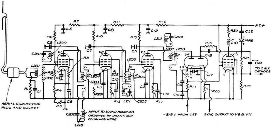
The first television set observed in a household around 1950 was constructed from a kit by the father of the narrator. It was housed in a box and featured a single channel, BBC, broadcasting at 45 MHz. Despite the...
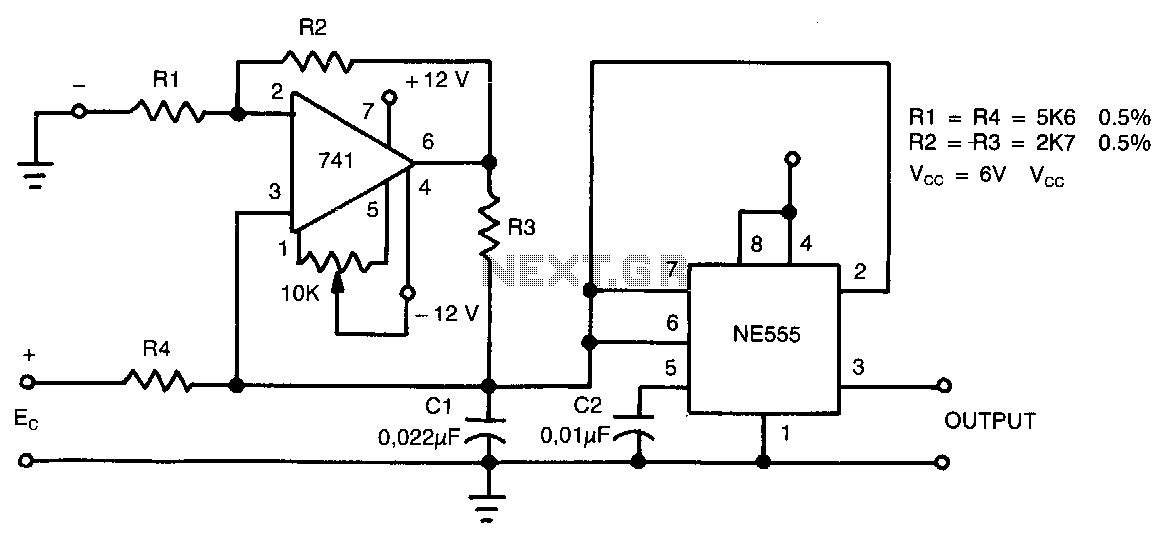
This circuit can accept positive, negative, or differential control voltages. The output frequency is zero when the control voltage is zero. The 741 operational amplifier forms a current source controlled by the voltage Ec to charge the timing capacitor...

Frequency converter schematic, frequency to voltage converter schematic, frequency to voltage converter using TR, voltage to frequency converter application. A frequency converter is an essential electronic circuit that transforms frequency signals into corresponding voltage levels or vice versa. The frequency...
In battery-powered applications such as cell phones, PDAs, and digital cameras, an integrated DC-DC converter circuit solution provides multiple advantages regarding cost, size, and design complexity. A significant challenge in achieving a fully integrated solution is designing the frequency...
The circuit diagram illustrates two LT1398 operational amplifiers from Linear Technology utilized to generate buffered color-difference signals from RGB (red-green-blue) inputs. In this setup, the R input is received through a 75-ohm coaxial cable and directed to the non-inverting...