
Frequency converter circuit

A frequency converter is an essential electronic circuit that transforms frequency signals into corresponding voltage levels or vice versa. The frequency to voltage converter schematic is designed to provide a linear output voltage that is proportional to the input frequency. This is particularly useful in applications where frequency signals need to be monitored or processed, such as in signal processing or control systems.
The frequency to voltage converter using a transistor (TR) typically employs a configuration where the input frequency signal is fed into a transistor circuit. The transistor operates in a switching mode, converting the frequency variations into a varying voltage output. The output voltage can then be further processed or displayed, providing a clear representation of the input frequency.
On the other hand, the voltage to frequency converter application is designed to achieve the opposite function, where an input voltage signal is converted into a frequency output. This type of converter is useful in telemetry systems and for generating frequency-modulated signals. The circuit generally utilizes operational amplifiers and other components to ensure that the output frequency is accurately proportional to the input voltage.
Both types of converters can be integrated into various electronic systems, enabling effective communication, control, and monitoring of frequency-based signals. Proper design considerations include component selection, circuit stability, and the linearity of the conversion process, which are crucial for achieving desired performance in practical applications.Frequency converter schematic, frequency to voltage converter schematic, Frequency to Voltage Converter Using TR, Voltage to Frequency Converter Application 🔗 External reference
Related Circuits

This design outlines a fire alarm circuit that utilizes a light-dependent resistor (LDR) and a lamp to detect fire. The alarm is activated by sensing the smoke produced during a fire. When smoke is present, it obstructs light from...
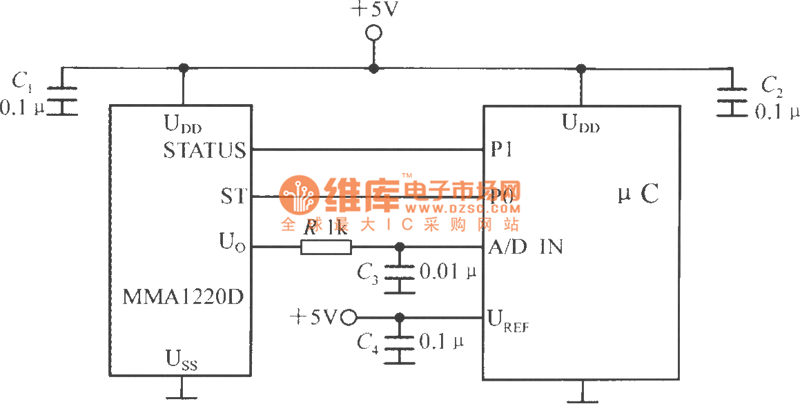
The microcontroller within the A/D converter can utilize a PIC MCU produced by Microchip. The MMA1220D's state and self-test pins are connected to the P1 and P0 ports of the microcontroller, with its output voltage sent to the input...

The two circuits illustrate the generation of low-frequency sine waves by shifting the phase of the signal through an RC network, enabling oscillation when the total phase shift reaches 360 degrees. The transistor circuit on the right produces a...
This controller is designed primarily for controlling model trains and can deliver approximately 12-15 Volts, though it operates effectively at voltages as low as 3V, including a 6V supply for certain accessories. The maximum output current is theoretically around...
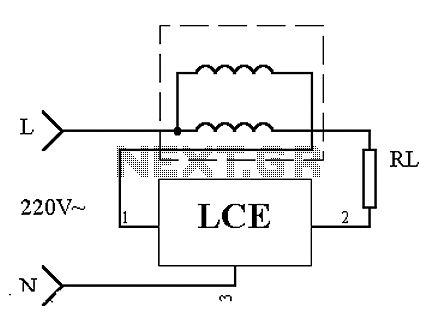
This is an application circuit of the device as illustrated in principle. In the meter, the voltage and current coils are connected to the power line, regardless of whether a load is connected. The voltage coil consistently draws power,...
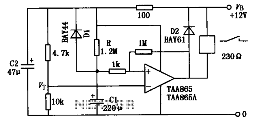
The circuit illustrated in the figure is a delayed release operational amplifier relay circuit. When the power switch is activated, a resistor of 4.7k is connected to the inverting input terminal of the operational amplifier. Additionally, a 10k resistor...