
Metal detector circuit diagram 2

The metal detector circuit operates by utilizing a combination of oscillation and amplification techniques to detect metallic objects. The power circuit supplies the necessary voltage and current, powered by batteries GBI and GB2, while filter capacitors C1 and C2 ensure a stable power supply by smoothing out any fluctuations. The power switch allows for the activation or deactivation of the entire circuit.
The sine wave oscillator generates a continuous sine wave signal, which is essential for the detection process. Transistor VI is responsible for amplifying the signal produced by the detecting coil (L), which is the primary sensor element of the metal detector. Capacitors C3 to C5 and resistors R1 and R2 are configured to set the frequency and stability of the oscillator.
The PLL circuit plays a crucial role in maintaining a consistent frequency for the detection process. This circuit includes a dual time-base integrated circuit that helps synchronize the output frequency with the incoming signals from the detecting coil. Resistors R3 and the adjustable potentiometer RP1 allow for fine-tuning of the phase-locked loop, while capacitors C6 to C8 stabilize the circuit's performance.
The hybrid amplifying circuit enhances the overall sensitivity of the metal detector. Transistors V2 and V3 amplify the detected signals, ensuring that even small metallic objects can be identified. Resistors R4 to R6 and potentiometer RP2 are used to adjust the gain of the amplifying stage, while the ammeter PA provides a visual indication of the signal strength.
Overall, this metal detector circuit combines various electronic components to create an effective and sensitive detection system, suitable for various applications in locating metallic objects. The use of carbon film resistors rated at 1/4W or 1/8W ensures reliability and precision in the circuit's operation.The metal detector circuit is composed of the power circuit, sine wave oscillator, PLL phase-locked loop circuit and hybrid amplifying circuit, and the circuit is shown as the chart. Power circuit is composed of the batteries GBI, GB2, filter capacitors C1, C2, and the power switch s (Sa, Sb).
Sine oscillator circuit consists of transistor VI, det ecting coil L, capacitors C3 ~ C5 and resistors RI, R2. PLL phase-locked loop circuit IC consists of dual time-base integrated circuit and resistos R3, potentiometer RP1, capacitors C6 ~ C8. Hybrid amplifying circuit is composed of the transistors V2, V3, resistors R4 ~ R6, potentiometer RP2 and ammeter PA.
R1 ~ R6 use l/4W or l/8W carbon film resistors. 🔗 External reference
Related Circuits
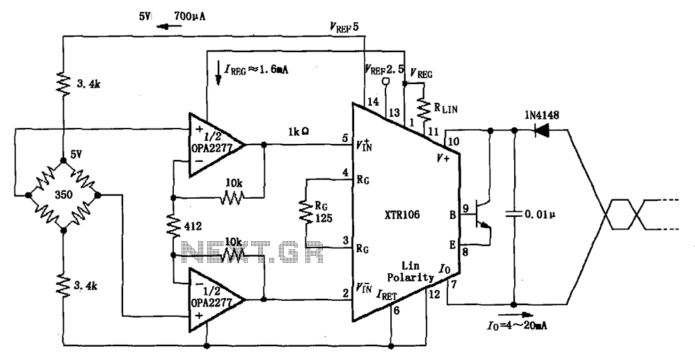
The XTR106, as illustrated in the figure, features two internal source voltages of 2.5V and 5V, enabling it to accommodate a wide range of bridge values without the need for additional circuitry. It can operate with bridge resistances lower...
This circuit is designed to indicate, via a flashing LED, when room noise exceeds a predetermined threshold, selectable from three fixed levels: 50 dB, 70 dB, and 85 dB. The circuit utilizes two operational amplifiers to amplify the sound...
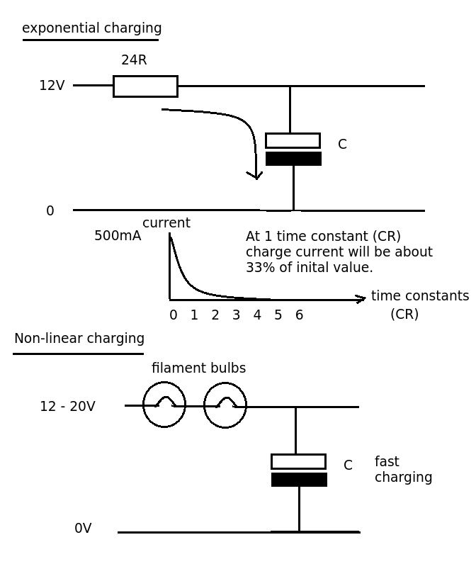
Designing a simple current limiter that charges a large 4.7mF capacitor with a charge current of approximately 500mA from a supply voltage of 10-20V. The dilemma is that there are existing MMBT2222A transistors available, which would be preferable to...
This circuit addresses the issue of phone line interruptions caused by simultaneous use of a modem or fax machine when another phone is picked up. It indicates the status of the phone line by illuminating a red LED when...
This project involves outdoor LED solar garden lights, which function as an automatic garden lighting system utilizing a light-dependent resistor (LDR) and a 6V/5W solar panel. During daylight hours, the internal rechargeable 6 Volt sealed lead-acid (SLA) battery is...
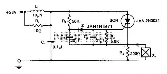
The LRC input network limits the anode dv/dt to a safe value below 30 V/μs. Rl provides critical damping to prevent voltage overshoot. While a simple RC filter section could be used, the high current required by the squib...