
The current loop interface circuit diagram of AD694 being used as D / A converter

The AD694 current loop interface circuit is designed to facilitate efficient communication between digital systems and analog devices. The architecture allows for seamless conversion from digital signals to analog outputs, which is crucial in various applications such as industrial automation, process control, and sensor interfacing.
The AD566A DAC, which is integral to this circuit, features a 12-bit resolution, enabling it to produce 4096 discrete output levels. This high-speed DAC ensures rapid conversion times, making it suitable for applications requiring quick response rates. The connection of the DAC output to the UI-end of the AD694 allows for direct integration, enhancing the overall performance of the signal conditioning process.
The dual ±15V power supplies are essential for the operation of the AD694, providing the necessary voltage levels for accurate signal processing and conditioning. The reference voltage supplied to the AD566A is critical for maintaining the precision of the output signal, ensuring that the DAC operates within its specified parameters.
The internal resistor network of the AD566A is a key feature that allows for the adjustment of the full-scale input to 10V. This configuration is particularly useful in applications where specific voltage levels are required for accurate signal representation. The inclusion of a frequency compensation capacitor (C2) helps stabilize the output by mitigating potential oscillations and ensuring consistent performance across various operating conditions.
The full-scale adjusting potentiometer (RP) provides flexibility in tuning the output signal, allowing users to calibrate the circuit according to their specific requirements. The design eliminates the need for a fixed resistor, simplifying the setup and enhancing the adaptability of the circuit.
Overall, the current loop interface circuit of the AD694, in conjunction with the AD566A DAC, represents a robust solution for digital-to-analog conversion in sensor signal conditioning applications, ensuring high accuracy and reliability in various electronic systems.The current loop interface circuit diagram of AD694 multi-functional sensor signal conditioner being used as D / A converter. The current loop interface of AD694 being used as D / A converter (DAC) can achieve the conversion of digitalvalue †’voltage signal †’current signal.
DAC`s current loop interface circuit is shown as the chart. AD566A is high-speed 12-bit DAC, its output (DAC OUT) is connected to AD694`s UI-end, UI + is grounded. AD694 uses ± 15V dual supplies, and provides reference voltage to the AD566A. Internal resistor network of AD566A will set AD694 with 10V full scale input. C2 is the frequency compensation capacitor. RP is the full scale adjusting potentiometer, it has no need to use a fixed adjustment 50 © resistor to replace the potentiometer. 🔗 External reference
Related Circuits
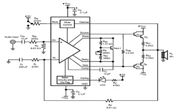
The LME49810 audio amplifier schematic is depicted in the accompanying circuit diagram. Based on the LME49810 datasheet, this component is a high-fidelity audio power amplifier driver intended for use in applications such as audio-video receivers, guitar amplifiers, powered studio...
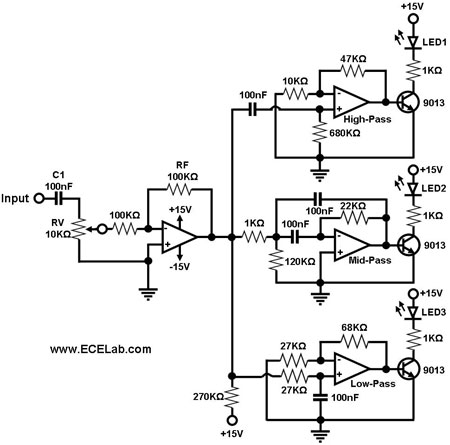
Figure 1 illustrates a simple circuit designed for converting an audio signal (such as one from the output terminals of a CD player). The circuit primarily consists of a buffer/amplifier stage and three filtering circuits: a high-pass filter, a...
The bi-directional sequencer utilizes a 4-bit binary up/down counter (CD4516) and two "1 of 8 line decoders" (74HC138 or 74HCT138) to create the well-known "Night Rider" display. A Schmitt Trigger oscillator generates the clock signal for the counter, with...
Have you ever attempted to copy a commercially produced video only to end up with a distorted and jumpy image? If so, then you have run afoul of MacroVision. MacroVision is the most popular copy protection scheme used on...
The function of this circuit is an audio amplifier capable of delivering a decent output power with a minimal number of components, with considerable efficiency. This audio amplifier circuit is designed to enhance audio signals, providing sufficient output power while...
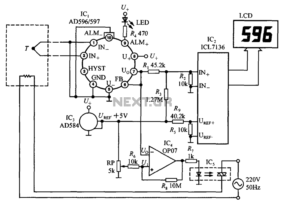
The circuit using AD596/597 forms a temperature measurement and control instrument. In this setup, AD596/597 (IC1) functions as a closed-loop thermocouple signal conditioner. IC2 is a monolithic CMOS 3 1/2 bit A/D converter ICL7136, which can also replace ICL7106,...