
18 W MOSFET Amplifier Circuit With BC550C Transistor

This audio amplifier circuit is designed to enhance audio signals, providing sufficient output power while maintaining a simple and efficient design. The circuit typically consists of a few essential components, including transistors, resistors, capacitors, and a power supply, which work together to amplify the input audio signal.
The core of the amplifier is usually a class AB transistor configuration, which combines the advantages of both class A and class B amplifiers. This configuration allows the circuit to produce high-quality audio output with reduced distortion levels. The transistors are responsible for increasing the input signal's amplitude, while the accompanying resistors and capacitors help to stabilize the circuit and filter out unwanted noise.
The power supply for the amplifier is critical, as it must provide adequate voltage and current to ensure optimal performance. Typically, a dual power supply is employed, allowing the amplifier to function effectively in both positive and negative voltage swings, which is essential for audio signals.
In addition to the basic amplification function, various feedback mechanisms may be incorporated into the circuit to improve linearity and reduce distortion further. This feedback can be achieved through the use of additional resistors and capacitors strategically placed in the circuit design.
Overall, this audio amplifier circuit is an efficient and straightforward solution for amplifying audio signals, making it suitable for various applications, including personal audio systems, small public address systems, and other audio-related projects.The function for this circuit is an audio amplifier capable of delivering a decent output power with a minimum no: of parts , with considerable .. 🔗 External reference
Related Circuits
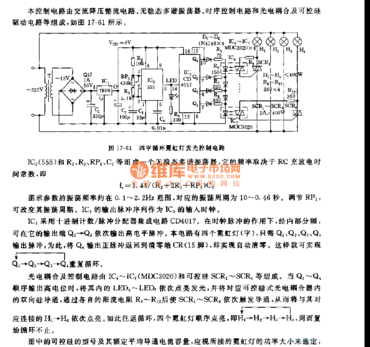
This control circuit consists of an AC step-down rectifier circuit, an astable multivibrator, a timing control circuit, an optocoupler circuit, and an SCR driving circuit, as illustrated in Figure 17-61. The astable multivibrator is formed using IC2 (555), resistors...
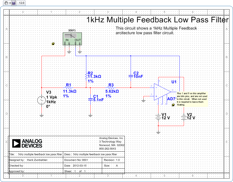
Pins 1 and 5 on this amplifier are trim pins and are not utilized in the circuit. When not in use, it is necessary to leave them floating. In electronic amplifier circuits, trim pins are often included for calibration or...
This page provides basic information about voltage comparator integrated circuits and is to act as reference material for other circuits. The circuits shown are based on the LM339 Quad Voltage Comparator chip or the LM393 Dual Voltage Comparator chip....
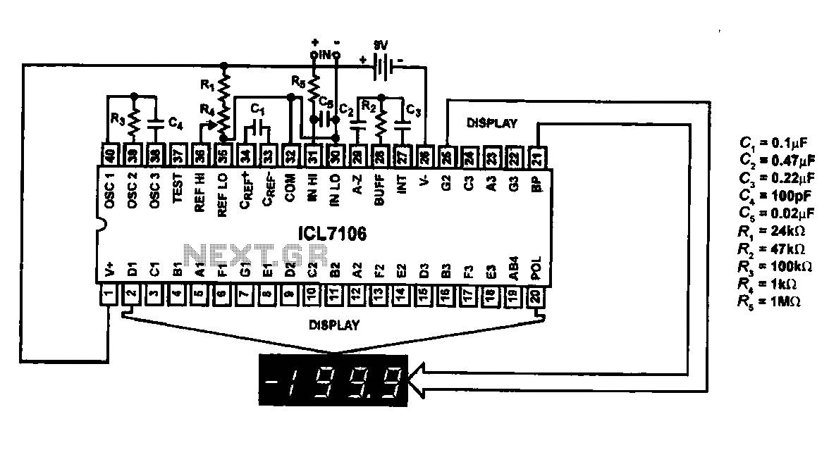
This circuit utilizes the ICL7106 / ICL7107 chip to drive a liquid crystal display (LCD). In this configuration, the ICL7106 / ICL7107 functions as a signal measurement and analog-to-digital (A/D) converter. It detects an analog input signal, amplifies it,...
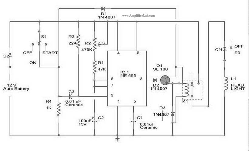
The circuit diagram for the automatic headlights turn-off circuit is presented here. This circuit can be installed in a car. The automatic headlights turn-off circuit is designed to enhance vehicle safety and convenience by ensuring that the headlights are automatically...
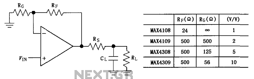
The circuit depicted in the figure employs the MAX4108/4109/4308/4309 operational amplifiers with a capacitive load driving circuit isolation resistor (Rs). While the MAX4108/4109/4308/4309 exhibits excellent AC characteristics, it is not optimized for driving high-load electrical resistances. A significant reactive...