
The Digital Sketchbook Arduino Frequency Measurement Library

The described project integrates various software and hardware components to create a comprehensive audio analysis tool. The use of software oscilloscopes, such as WaveWindow and Signal Scope, facilitates the visualization of waveforms, which is essential for audio engineers and enthusiasts. The incorporation of the FFT Analyzer allows for detailed spectral analysis, enabling users to examine multiple signals concurrently, which is crucial for complex audio work.
The Project Hijack board exemplifies innovation in mobile technology, allowing for the development of compact sensor peripherals that can easily interface with mobile devices. This platform opens new avenues for creating low-cost sensor applications that leverage existing mobile technology, enhancing the functionality of smartphones and tablets.
The DIY frequency measurement solution from the Academy of Media Arts Cologne showcases the effectiveness of the ATMEGA chip in precision applications. Its ability to measure frequency accurately in the sub-audio range is particularly valuable for audio engineers looking to analyze low-frequency signals. The challenges faced in signal amplification and the eventual resolution through direct audio routing highlight the importance of understanding circuit design and signal integrity.
The project’s documentation process using Fritzing ensures that the design is reproducible and clear, which is essential for sharing knowledge within the electronics community. The transition from breadboard to PCB design illustrates the development process, emphasizing the iterative nature of electronic design. The final assembly, including the acrylic case, not only protects the components but also provides a user-friendly interface with the inclusion of an LCD display and control button, enhancing the overall usability of the device. This project represents a successful blend of software and hardware engineering, resulting in a versatile audio analysis tool suitable for various applications.software on my MacBook Pro - such as the aforementioned Laidman & Katsura `s WaveWindow - WaveWindow is a software oscilloscope. It`s useful for anyone who works with sound on the Mac; it`s educational and fun to play with. and Faberacoustical `s Signal Scope - Oscilloscope - Digitize and visualize multiple waveforms and FFT Analyzer - Analy
ze narrowband spectral content. 16 signals at a time. ; software on my iPod Touch such as Oscilloscope (there`s a hardware hack required to create an audio line in - by cutting up and soldering sockets onto a cheap iPhone headset) - though I`ve just found out that the Project Hijack board I`ve been wanting to try out for a while - HiJack is a hardware/software platform for creating cubic-inch sensor peripherals for the mobile phone. HiJack devices harvest power and use bandwidth from the mobile phone`s headset interface. The HiJack platform enables a new class of small and cheap phone-centric sensor peripherals that support plug-and-play operation.
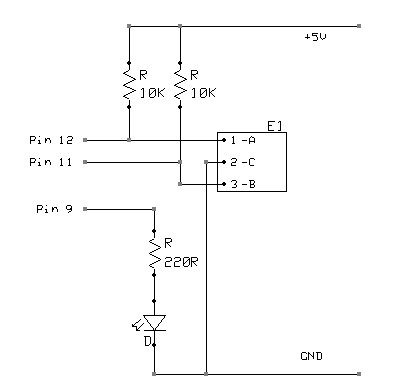
HiJack has been tested with the iPhone 3G/3GS/4G, iPod Touch, and iPad devices. is now available as part of the Hijack Development Pack from Seeed Studio for $79; and my favoured DIY solution - the Academy of Media Arts Cologne: Laboratory for Experimental Computer Science: labIII Frequency Measurement Library For frequency measurement in the audio or sub audio range the determination of the signal period length delivers the most accurate results. The architecture of the ATMEGA chip provides a special Counter and Capture unit which is designed todo this job with a high precision.
particulalry since Compared to a Frequency Counter Library published here before, this method delivers a higher accuracy and speed in the range below 20 KHz. it seemed an ideal solution. Following the schematic I built the circuit on a breadboard and tested the code and it worked result.
However, it took a little while to discover that it needed a relatively high signal input level. Initially I tried the two preamplifier schematics from the Frequency Counter library (after consulting the Transistor - Wikipedia, the free encyclopedia article to work out how to actually wire it up) hoping they could boost signal levels without introducing too much noise - but they didn`t - so I ended up routing audio directly from the AD9835 and before the volume pot. I tweaked the code to additionally output a Running Average and two alternatively calculated Running Median values of the frequency to even out occasional spikes and glitches in the measurement.
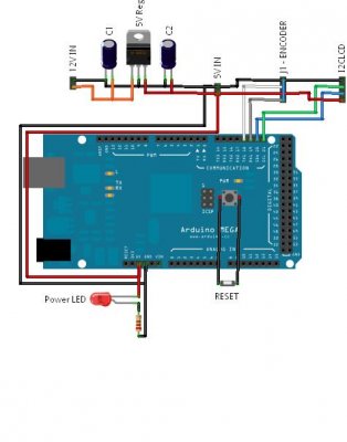
Determined to actually use the SpikenzieLabs I2C LCD Interface kit mentioned in an earlier post, I persevered with the clunky demo code and eventually managed to display the output on an old 16x2 LCD display - adding a button to switch between the various output types. I then used Fritzing to document the breadboard circuit, produce a clear schematic and design a PCB layout of the various components as a simple Arduino shield - which I tried to make using sticky backed copper foil cut on the vinyl cutter at Fab Lab Manchester.
My first attempt at this didn`t work too well - but I`ve subsequently cut more promising versions - though I ended up using a DFRobot. com Prototyping Shield for Arduino to mount the components and connection headers instead - albeit it fried my head a little since it has a specific pad and 5V/GND line layout but which I was pleased to find worked first time once I`d soldered it all up ;-) Finally, I laid out and laser cut an acrylic case using my adaptable Arduino enclosure design for the Super DMX Shield box I made for Monomatic.
It houses the Arduino and shield; a 9V battery, power switch and LED; and in the top plate - the button and a 16x2 LCD display holder inspired by the Spikenzielab`s curved LCD Stand. 🔗 External reference
Related Circuits
The requirement was to add a digital readout to a manually operated bend roller machine to accurately monitor the amount of material fed into the machine. The readout should be user-friendly, requiring no setup other than initial calibration, and...
Construct different power conversion circuits using an Arduino microcontroller. The Arduino microcontroller serves as a versatile platform for developing various power conversion circuits. These circuits can include DC-DC converters, AC-DC converters, and other forms of power management systems. The flexibility...
A rotary encoder generates two square wave outputs (A and B) that are 90 degrees out of phase. The number of pulses or steps produced per full rotation varies by model; for instance, the Sparkfun Rotary Encoder has 12...
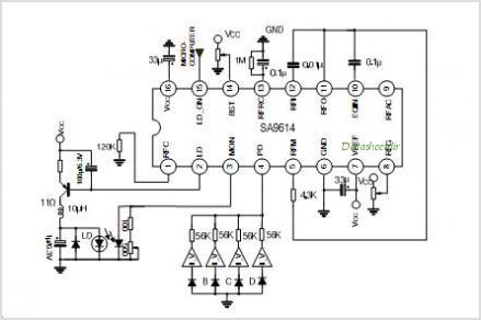
The SA9618A is designed for ALPC and signal conversion between a CD optical pickup and a decoding chip. This integrated circuit (IC) features an interconnection for a general CD optical pickup photodiode bias voltage VREF generation circuit, an RF...
The circuit above makes use of the CMOS 4017 decade counter IC. Each depression of a switch steps the output through 0 - 9. By coupling the output via an AND gate to the next IC, a predefined code...
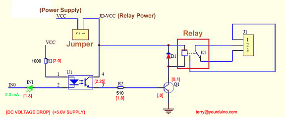
Control a relay from an Arduino-compatible board. When attempting to activate the relay from the Arduino, it takes at least a second to close, and sometimes it does not close at all. Digital pin 2 of the Arduino is...