
Using an Arduino in a Production environment

The electronic schematic for this project can be broken down into several key components and their interconnections. The power supply unit, a Traco TXL SMPSU, converts mains AC voltage to 12V DC, which is distributed to the various components. The Arduino Mega serves as the central processing unit, receiving power through a 5V regulator circuit derived from the 12V supply. This regulator is mounted on a small matrix board, ensuring stable operation of the Arduino and the connected LCD.
The Hewlett Packard optical encoder, characterized by its 360 pulses per revolution (ppr), is connected to the Arduino via digital input pins to facilitate pulse counting. This encoder is crucial for measuring the distance the workpiece travels through the rollers. The encoder’s output is processed by the Arduino to maintain an accurate count of revolutions, which is then translated into a linear measurement displayed on the LCD.
The chosen 20x4 Black/Green LCD features a selectable Serial/I2C interface, which minimizes wiring complexity to just four connections: two for power (VCC and GND) and two for data communication (SDA and SCL). This interface allows for efficient data transfer between the Arduino and the display, ensuring real-time updates of the measured distance.
The reset functionality is achieved through an external switch that connects to the Arduino's onboard reset pin, allowing the user to zero the display easily. The software implemented in the Arduino is programmed to handle pulse counting, conversion to linear measurements, and display updates. The code also includes debugging features to monitor memory usage, which assists in identifying and resolving any issues that may arise during operation.
Overall, the schematic integrates these components into a cohesive system that meets the requirements of the bend roller machine, providing a reliable and cost-effective solution for monitoring material input.The requirement was to add a digital readout to an otherwise manually bend roller machine so that we could accurately monitor the amount of material fed into the machine. The readout should be simple to use, require no setup other than initial calibration and above all be reliable.
First a little background on me, I`m a Mechanical design engineer by training but I`ve always had a `thing` for software and electronics. I`ve dabbled in electronics at a hobby level for a number of years so as you can see I am by no means an electronics or software expert. I thought I would document my use of an Arduino (see here for the Arduino software and hardware ) in an industrial production environment as I felt it demonstrated what it is possible to achieve with limited experience.
Traditionally this sort of project would have been prohibitively expensive and would require both electronics hardware and software experience but by using an Arduino Mega and some off the shelf components it is possible to produce a usable solution to the problem without excessive cost. The main unit is mains powered via a Traco TXL SMPSU this feeds a 12V DC to a small matrix board containing a 5V regulator circuit to power the Arduino and LCD.
The encoder was powered from the 12V DC. The encoder is a Hewlett Packard panel mount optical encoder with 360ppr (pulse per rev) and is available from RS Components (205-6853). The documentation is the usual concise HP offering and gives all the relevant details of the device. The display I selected was a 20 x 4 Black/Green LCD with a selectable Serial / I2C interface. This was chosen to simplify the interfacing with the Arduino (only 4 wires required) The workpiece is setup in the rollers and the display is zeroed using the Reset button, the workpiece is fed through the bend rollers until the required distance has been travelled.
The Arduino counts the pulses coming from the encoder and increments or decrements a counter, the Arduino converts the counter value to a linear measurement and displays it on the screen. The conversion factor needed a little tweaking in the final unit but this was covered by the simple one off calibration process during commissioning.
To zero the display I originally intended to have the reset button connected to one of the digital input pins and then reset the pulse counter to zero, however as I was writing the code I noticed that the start-up time of the Arduino was so fast that I might as well just use the on-board reset function and reset the entire Arduino. So I connected my external switch across the on-board reset button, a little crude perhaps but it works.
The only real problem was with an offending piece of code which gradually caused a heap overflow forcing the Arduino to reset itself, certainly not a desirable situation. I managed to find some very useful code which streamed memory stats to the serial port where I could display the results on my PC.
With this I could debug the code until I found the offending section (part of the i2c display code I had imported) and replace it. On the whole the project went well, it allowed me to fulfil a production requirement without tying up valuable electronics design engineers on a non revenue earning internal project.
If you`d like a copy of the code please drop me an email and I`ll send it to you. the code is supplied as is, with no warranty or guarantees as to its suitability or stability. 🔗 External reference
Related Circuits

The difference between instantaneous frequency and central frequency of the carrier is directly proportional to the instantaneous value of the amplitude of the message signal. A 555 Timer configured in Astable Mode can be utilized for generating Frequency Modulated...
The emitter will consistently be a few hundred millivolts lower than the base voltage in this configuration. With the base voltage set at 5V, the emitter voltage is likely to be around 4.5V, depending on the current drawn by...
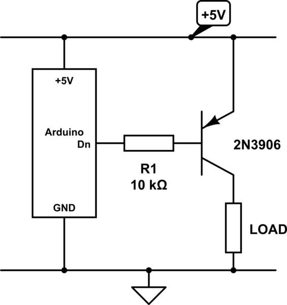
The Arduino microcontroller board can supply a current of 40mA from its output connections, with digital outputs fixed at 5V for "ON" and 0V for "OFF." This current is suitable for LEDs, but devices like motors, solenoids, and high-brightness...
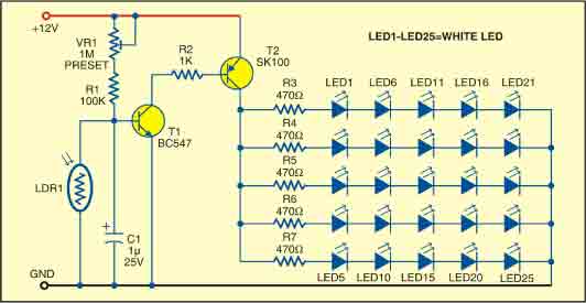
This sunlight-controlled lamp utilizes a light-dependent resistor (LDR) as the sunlight sensor and comprises a total of 25 high-brightness white LEDs. Each row of LEDs is connected in series with separate resistors. The operation of the circuit is straightforward....
System Oscillator Crystal/Ceramic Oscillator. The following circuit combination of resistors, capacitors, and inductors depicts an equivalent circuit for a crystal or ceramic oscillator. The system oscillator, specifically a crystal or ceramic oscillator, utilizes a combination of passive components, including resistors,...
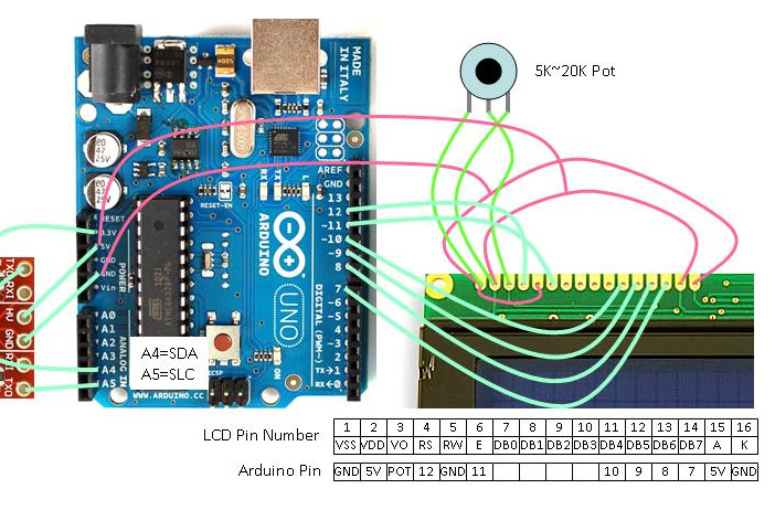
For an effective tutorial on connecting a standard LCD to an Arduino and utilizing the standard LCD library, refer to the LadyAda Tutorial on LCDs. The diagram illustrates the fundamental connections with a standard LCD that is compatible with...