
The dual-way control SCR liquid level control circuit

The circuit operates by monitoring the water level through the three detection poles. The poles are strategically placed at different heights to provide a range of water level detection. The bias circuit is established using resistors R1, R2, and R3 in conjunction with the water level sensor W1. The output voltage from the detection poles is compared to a reference voltage level derived from the supply voltage VDD.
When the water level is above pole b, the voltage across R3 remains sufficiently high, preventing the 555 timer from triggering. However, as the water level drops below pole b, the voltage divider effect created by the resistors results in a voltage that falls below the threshold of 1/3 VDD. This triggers the 555 timer, which is configured in a monostable mode, leading to a change in its output state.
The triggered output from the 555 timer activates the SCR (Silicon Controlled Rectifier), which allows current to flow through the load circuit. This mechanism can be utilized for various applications such as activating a pump to refill the water tank or turning on an alarm system when water levels are critically low. The step-down rectifier circuit ensures that the control circuit operates at a safe voltage level, providing the necessary power for the entire system while protecting sensitive components from over-voltage conditions.
In summary, this circuit effectively combines a liquid level detection system with a control mechanism that can respond dynamically to changes in water levels, demonstrating a robust solution for automated water management systems.See as the figure, the controller consists of liquid level, trigger controller and step-down rectifier circuit, etc. The water level detecting poles of a, b and c compose the bias circuit as the water level detector with W1, R1, R2 and R3.
When the water level is below b, Vp-b?R3×VDD/?Rw1+R1+R2+R3?<1/3VDD, 555 is offset, SCR is triggered and conduct.. 🔗 External reference
Related Circuits
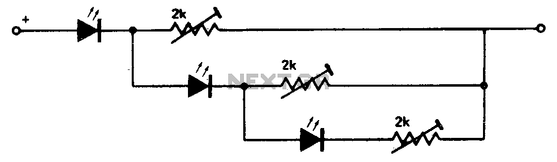
This circuit creates a compact level indicator suitable for situations where a traditional meter would be impractical or cost-prohibitive. The resistor values are contingent upon the type of LED utilized. For MV50 LEDs, resistor values of 2 kΩ are...
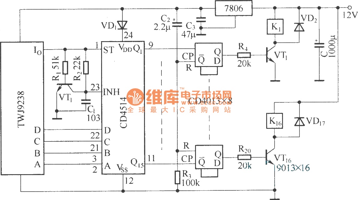
The Sixteenth Street control circuit consists of a secondary decoding output control circuit. Each output terminal of the sixteen decoding is connected to a bistable circuit made up of dual D flip-flops (CD4013). A DC relay is connected to...
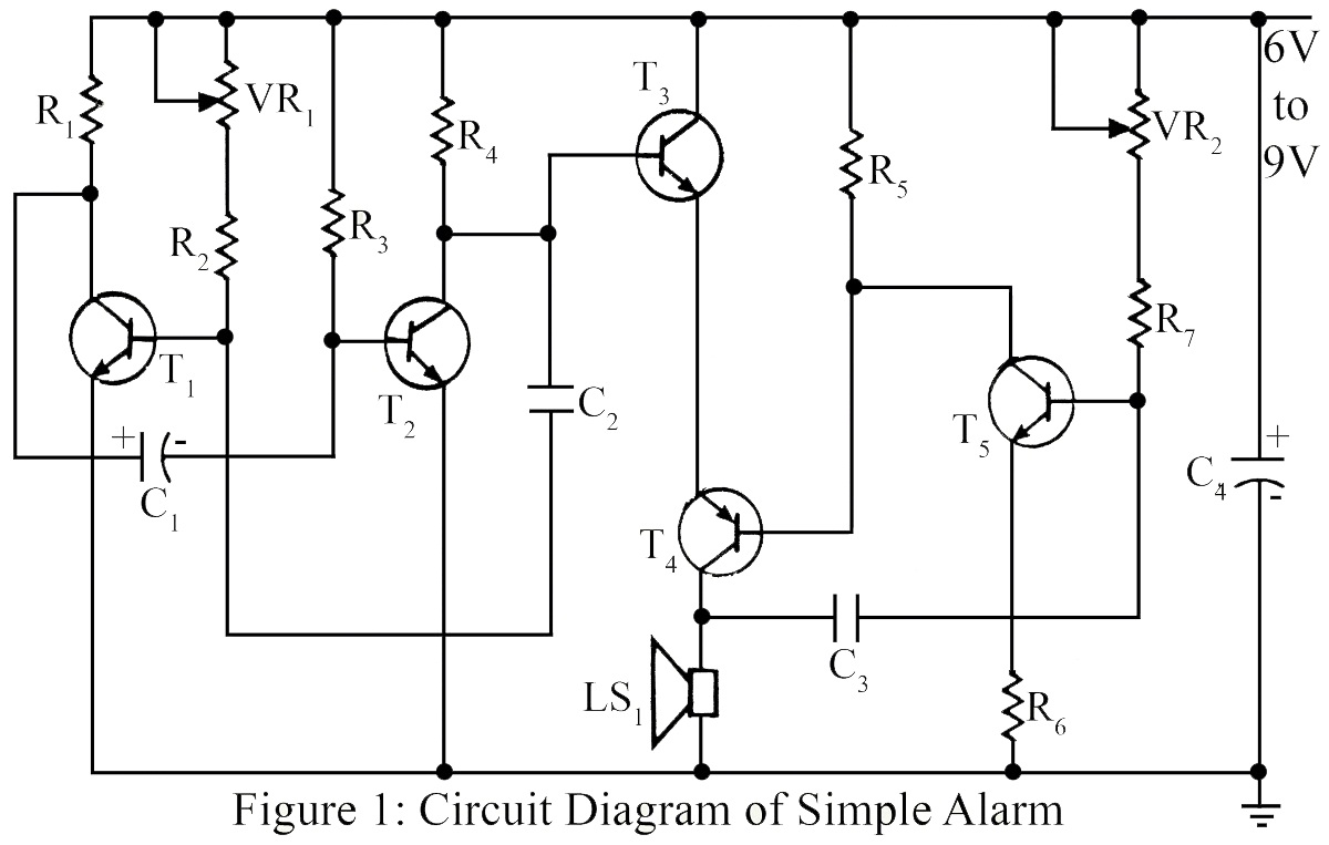
The simple circuit generates an audible alarm notification, functioning as a burglar alarm utilizing five transistors. This circuit operates as a basic burglar alarm system designed to emit an audible sound when triggered. The core component of the circuit is...
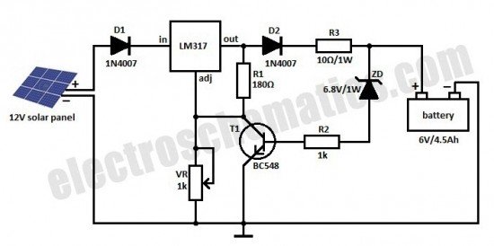
This is a solar charger circuit designed to charge Lead Acid or Ni-Cd batteries using solar energy. The circuit captures solar energy to charge the batteries. The solar charger circuit typically consists of several key components, including a solar panel,...
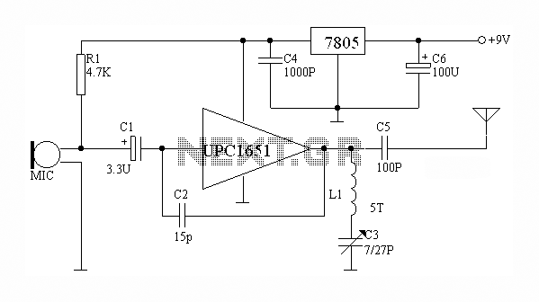
The circuit depicted utilizes the UPC1651 integrated circuit produced by NEC Corporation of Japan. It offers high gain and stability, ensuring optimal performance for microphones. The design incorporates an FM transmitter circuit. The system employs a flexible antenna measuring...
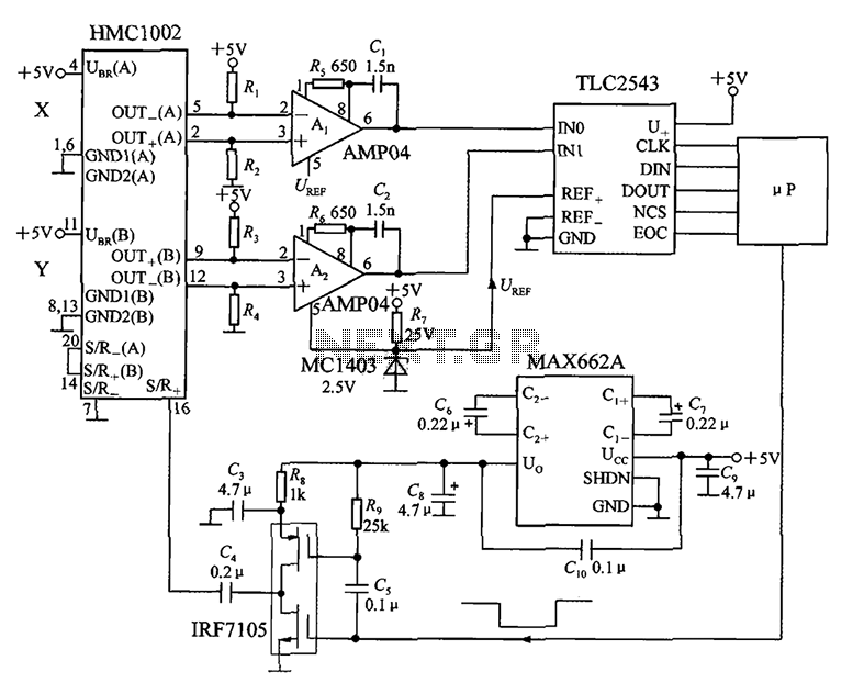
An application circuit for a biaxial magnetic field sensor is presented. This circuit utilizes the HMC1002 biaxial magnetic sensor along with two AMP04 amplifiers (A1, A2) to simultaneously measure magnetic fields in both the X-axis and Y-axis directions. The...