
The Gentle Touch

The circuit design operates using a microcontroller to manage the power state of devices without a conventional mains switch. The p-channel MOSFET (T1) acts as a high-side switch, while the n-channel MOSFET maintains the state of T1 after the initial button press. The circuit begins in an off state, conserving energy until the user initiates a power-on sequence by pressing the pushbutton. The microcontroller must be programmed to handle debounce logic to prevent false triggering caused by mechanical bounce in the switch.
The voltage divider formed by resistors R1 and R2 is critical for setting the appropriate gate voltage for T1. The values of these resistors must be calculated based on the input voltage to ensure that the gate-source voltage remains within safe operating limits for the MOSFET. The choice of MOSFETs is essential, as they must handle the expected load current without overheating or failing.
In battery-powered applications, placing the switch before the voltage regulator optimizes power efficiency, as it completely disconnects the load when off, while for mains-powered devices, careful consideration of standby current is necessary to minimize energy waste. The firmware for the microcontroller should include routines for initializing the I/O ports, handling button state changes, and ensuring that the device responds correctly to user inputs while maintaining system stability.
Overall, this design provides a practical solution for modern appliances, allowing for remote control functionality without compromising energy efficiency.Consumer appliances these days hardly ever have a proper mains switch. Instead, appliances are turned on and off at the touch of a button on the remote control, just like any other function. This circuit shows how a device (as long as it does not draw too high a current) can be switched on and off using a pushbutton.
The approach requires that a m icrocontroller is already available in the circuit, and a spare input port pin and a spare output port pin are required, along with a little software. When power is applied T1 initially remains turned off. When the button is pressed the gate of T1 is taken to ground and the p-channel power MOSFET conducts.
The microcontroller circuit is now supplied with power. Within a short period the microcontroller must take output PB1 high. This turns on n-channel MOSFET T1 which in turn keeps T1 turned on after the push-button is released. Now the microcontroller must poll the state of the push-button on its input port (PB0) at regular intervals.
Immediately after switch-on it will detect that the button is pressed (a low level on the input port pin), and it must wait for the button to be released. When the button is next pressed the device must switch itself of f: to do this the firmware running in the microcontroller must set the output port pin to a low level.
When the button is subsequently released T1 will now turn off and the supply voltage will be removed from the circuit. The circuit itself draws no current in the off state, and for (rechargeable) battery-powered appliances it is therefore best to put the switch before the voltage regulator.
For mains-powered devices the switch can also be fitted before the voltage regulator (after the rectifier and smoothing capacitor). Since there is no mains switch there will still be a small standby current draw in this case due to the transformer.
Be careful not to exceed the maximum gate-source voltage specification for T1: the IRFD9024 device suggested can withstand up to 20 V. At lower voltages R2 can be replaced by a wire link; otherwise suitable values for the voltage divider formed by R1 and R2 must be selected.
The author has set up a small website for this project at, which gives source code examples (which include dealing with pushbutton contact bounce) for AVR microcontrollers suitable for use with AVR Studio and GNU C. Downloads are also available at. 🔗 External reference
Related Circuits
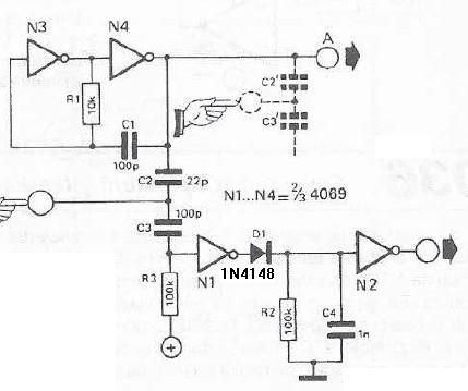
This touch sensor switch is designed using inverters (N1, N2) and several common electronic components. In the standby state, a signal is produced by the oscillator N3/N4 at the inputs of N1. When the touch sensor is activated, the...
Modern consumer appliances rarely include a conventional mains switch. Instead, these devices are activated and deactivated using a button on a remote control, similar to other functions. This circuit demonstrates how to control a device (provided it does not...
This project involves a 555 touch alarm circuit integrated with an UM66 melody IC. The circuit is designed to emit a melodious alarm sound for a predetermined duration when a person touches the metal plate or touch plate depicted...
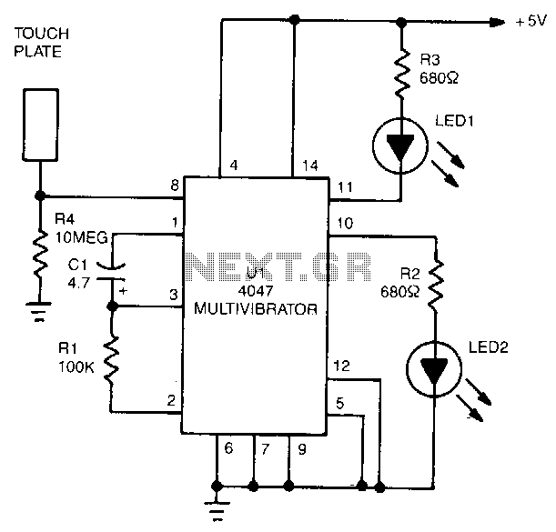
The 4047 is configured as a monostable multivibrator circuit, also known as a one-shot, which is triggered by a negative transition of the signal applied to its pin 6 input. The duration of the multivibrator's output pulse is determined...
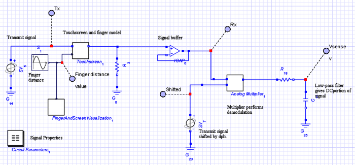
The objective of this project is to develop a model of a capacitive touch screen, which includes the physical modeling of a user's finger, the materials of the touch screen, and the touch-detection circuitry. A capacitive touch screen functions...
Capacitive touch sensors operate based on the electrical capacitance associated with the human body. When a finger approaches the sensor, it establishes a capacitance to the ground, typically ranging from 30 to 100 pF. This phenomenon can be utilized...