
The Gentle Touch

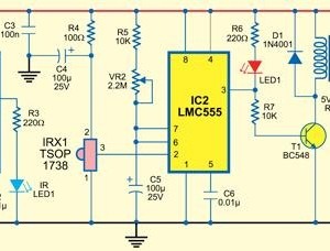
The circuit design employs a microcontroller to manage power to a device via a pushbutton interface. The p-channel MOSFET (T1) serves as a high-side switch, enabling or disabling power based on the microcontroller's state. The initial state of T1 is off, ensuring that the device remains powered down until the user initiates action via the pushbutton. Pressing the button connects the gate of T1 to ground, allowing current to flow and activating the microcontroller.
Once powered, the microcontroller must quickly set the output pin (PB1) high, which engages an n-channel MOSFET. This configuration allows the circuit to maintain power even after the pushbutton is released, effectively latching the state of the device on. The microcontroller continuously polls the input pin (PB0) to check the status of the pushbutton. When the button is pressed again, the microcontroller responds by setting the output pin low, which turns off T1 and consequently disconnects the power supply.
This design is particularly advantageous for battery-operated devices, as it eliminates power consumption when the device is off. For mains-powered devices, while a small current may still flow due to transformer characteristics, placing the switch before the voltage regulator minimizes potential waste. The circuit's efficiency is further enhanced by selecting appropriate resistor values for the voltage divider, ensuring that the gate-source voltage remains within safe limits for the MOSFET.
The implementation of debounce logic in the firmware is crucial to prevent false triggering caused by mechanical bounce in the pushbutton. This aspect is addressed in the provided source code examples, which can be adapted for various applications using AVR microcontrollers. Overall, this circuit exemplifies a modern solution for controlling consumer appliances without traditional switches, leveraging microcontroller capabilities for efficient operation.Consumer appliances these days hardly ever have a proper mains switch. Instead, appliances are turned on and off at the touch of a button on the remote control, just like any other function. This circuit shows how a device (as long as it does not draw too high a current) can be switched on and off using a pushbutton.
The approach requires that a m icrocontroller is already available in the circuit, and a spare input port pin and a spare output port pin are required, along with a little software. When power is applied T1 initially remains turned off. When the button is pressed the gate of T1 is taken to ground and the p-channel power MOSFET conducts.
The microcontroller circuit is now supplied with power. Within a short period the microcontroller must take output PB1 high. This turns on n-channel MOSFET T1 which in turn keeps T1 turned on after the push-button is released. Now the microcontroller must poll the state of the push-button on its input port (PB0) at regular intervals.
Immediately after switch-on it will detect that the button is pressed (a low level on the input port pin), and it must wait for the button to be released. When the button is next pressed the device must switch itself of f: to do this the firmware running in the microcontroller must set the output port pin to a low level.
When the button is subsequently released T1 will now turn off and the supply voltage will be removed from the circuit. The circuit itself draws no current in the off state, and for (rechargeable) battery-powered appliances it is therefore best to put the switch before the voltage regulator.
For mains-powered devices the switch can also be fitted before the voltage regulator (after the rectifier and smoothing capacitor). Since there is no mains switch there will still be a small standby current draw in this case due to the transformer.
Be careful not to exceed the maximum gate-source voltage specification for T1: the IRFD9024 device suggested can withstand up to 20 V. At lower voltages R2 can be replaced by a wire link; otherwise suitable values for the voltage divider formed by R1 and R2 must be selected.
The author has set up a small website for this project at, which gives source code examples (which include dealing with pushbutton contact bounce) for AVR microcontrollers suitable for use with AVR Studio and GNU C. Downloads are also available at 🔗 External reference
Related Circuits
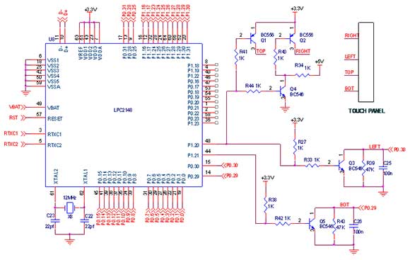
A touch screen is an electronic visual display capable of detecting the presence and location of a touch within its display area. This term typically refers to the interaction with the device's display using a finger or hand, although...
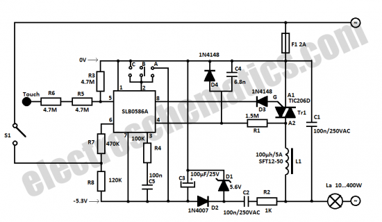
The SLB0586A integrated circuit from Siemens can be utilized to construct a straightforward touch light dimmer circuit, enabling the user to modify the intensity of a lamp. This circuit also incorporates a TIC206D component. The SLB0586A is a specialized touch-sensitive...
When the touch plate is activated by a large object, such as a human body, stray 60 Hz pickup is rectified by diodes D1 and D2, resulting in a negative voltage across resistor R2 and capacitor C2, which affects...
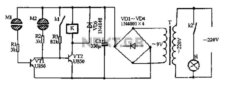
After the power is turned on, 220V AC is stepped down by transformer T. The output is then rectified by the VD1 to VD4 bridge rectifier and filtered by C1 to produce approximately 10V DC voltage for the Darlington...
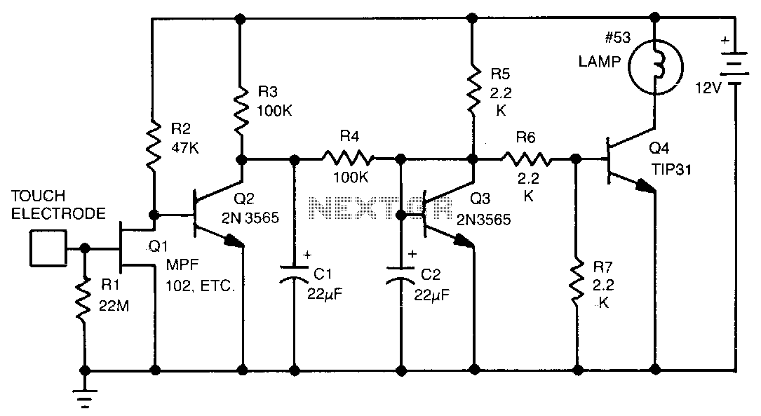
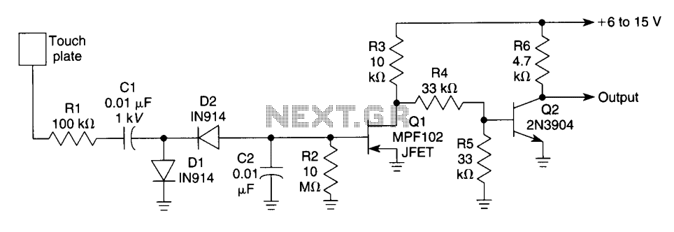
This touch-activated switch remains in the 'on' state as long as the user's finger is in contact with the touch plate. Resistor R1 establishes a high input impedance of 22 MΩ. Transistor Q1 detects stray signals that are coupled...
This type of infrared proximity circuit is commonly utilized as an electric switch where physical contact is undesirable for hygiene reasons. For instance, infrared proximity sensors are frequently found in public drinking fountains and washrooms. The straightforward circuit described...