
The H-Bridge

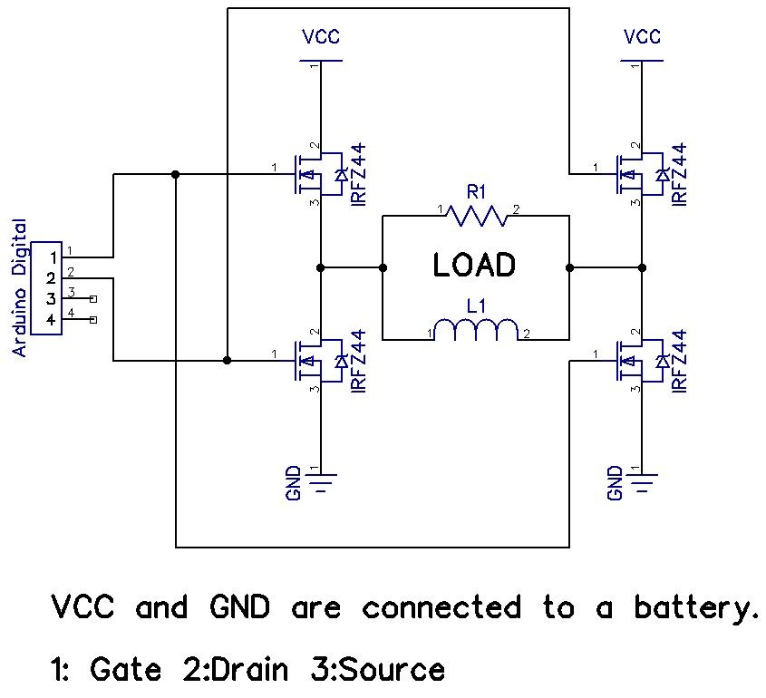
The Snap Circuits Motor Control IC is designed to control the direction and speed of DC motors using an H-bridge configuration. An H-bridge consists of four switches that can be transistors, MOSFETs, or relays, which allow the voltage to be applied across the motor in either direction, thus enabling forward and reverse motion.
In the schematic, the inputs to the H-bridge are typically connected to a microcontroller or a control circuit that generates the necessary signals to switch the transistors on and off. The control signals determine the operation of the motor by adjusting the duty cycle of the PWM (Pulse Width Modulation) signals, which in turn controls the speed of the motor.
The H-bridge may include additional features such as current sensing, thermal protection, and over-voltage protection to ensure safe operation. Often, diodes are included in the design to protect against back EMF generated by the motor when it is turned off or when it changes direction.
The layout of the circuit should ensure that the traces carrying high current are sufficiently wide to handle the load without overheating, and the ground connections should be robust to minimize noise and ensure stable operation. Proper decoupling capacitors may also be placed near the power supply pins to filter out any voltage spikes.
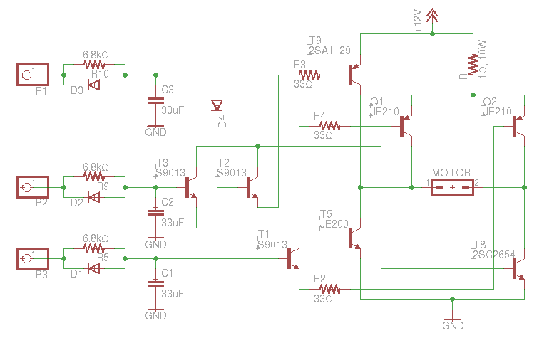
Overall, the Snap Circuits Motor Control IC is a versatile component for educational projects and prototyping, allowing users to easily integrate motor control functionality into their designs.This is the Snap Circuits Motor Control IC, or H-bridge. At the top of the figure you can see the electronic schematic of the Motor Control block. On.. 🔗 External reference
Related Circuits

The 10A H-Bridge Motor Controller circuit appears straightforward, but several critical aspects should not be overlooked. The primary components utilized in the circuit include the TIP147, TIP142, and 2N2222 transistors. The power supply circuit operates at +12V, which is...
An old RC car is available, but it lacks the transmitter. A custom receiver/transmitter has been built using a microcontroller and a 2.4 GHz transceiver. However, there is uncertainty regarding the functionality of the car's original H-Bridge circuit. The H-Bridge...
The objective is to enhance information transmission through the use of articles. Please contact us via email at [email protected] within 15 days if there are any issues related to article content, copyright, or other concerns. Prompt action will be...
The H-Bridge is a circuit that can drive a motor in both forward and reverse directions. It can be a straightforward circuit that requires only a few components. The H-Bridge circuit is a fundamental configuration used in motor control applications,...
An H-bridge is being utilized with IRF740 MOSFETs to convert 315V DC to 230V AC. However, the upper MOSFETs are frequently damaged within a few seconds, and the cause of this issue has not been identified. The described circuit employs...
The interface uses a PIC16F876 microcontroller and not much else. It performs channel mixing, current limiting, and noise rejection. Push the stick forward, both motors move forward, move the stick to the left and the robot moves left. It...