
The ICL7135 Integrating A/D Converter Functional Diagram and Datasheet

The ICL7135 is a highly integrated analog-to-digital converter designed for precision measurement applications. It employs the dual-slope integration technique, which is particularly advantageous for applications where noise reduction is critical, such as in digital voltmeters and panel meters. The dual-slope method works by integrating the input signal over a fixed period, followed by a reference voltage integration over the same duration. This approach effectively cancels out noise and provides high accuracy in voltage measurement.
The functional diagram of the ICL7135 illustrates its key components, including the input stage, integrating capacitor, comparator, and control logic. The input stage is responsible for conditioning the analog signal before it is fed into the integrator. The integrator uses a capacitor to accumulate the input voltage over time, while the comparator continuously monitors the integrated voltage against a reference level. When the integrated voltage reaches the reference, the system switches to the reference integration phase, allowing for precise measurement of the input signal.
The ICL7135 is designed with features that enhance its performance, including high input impedance, low offset voltage, and excellent linearity. These characteristics make it suitable for a wide range of applications beyond just panel meters, including industrial automation, laboratory instrumentation, and consumer electronics. The datasheet provides a wealth of information, including detailed sections on the dual slope technique, simplified circuit diagrams for implementation, and specifications for the analog section of the converter.
Overall, the ICL7135 stands out as a versatile and reliable choice for high-precision analog-to-digital conversion, particularly in environments where minimizing noise and maximizing accuracy are of paramount importance.The schematic below showsthe ICL7135 integrating analog to digital converter (ADC) functional diagram. According to the datasheet, an integrating converter is the right choice for panel meters and digital voltmeter applications.
It also can be used for reducing line frequency noise since it has very good rejection of frequencies. In theICL7135 dat asheet, you will find sections for such the description of dual slope technique (theory and practice), simplified dual slope converter circuit diagram, analog section of dual slope converter, and more. 🔗 External reference
Related Circuits
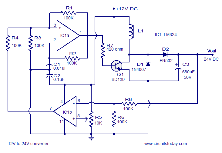
A simple 12V to 24V DC-DC converter circuit diagram built around the LM324. This boost converter schematic can provide up to 800mA output current and a steady 24V DC. The described circuit utilizes the LM324 operational amplifier as the core...
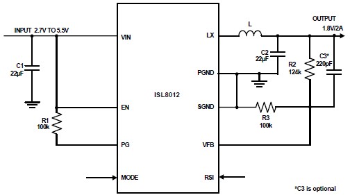
The ISL8012 is a high-efficiency, monolithic, synchronous step-down DC-DC converter that can be designed into a simple electronic project. It supports a maximum continuous output current of up to 2A from an input supply range of 2.7V to 5.5V....
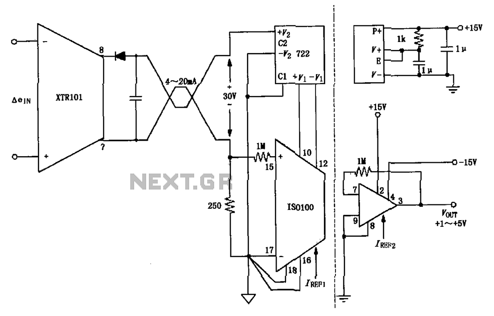
The circuit combines the XTR101 with the ISO100 isolation amplifier to transform a 4-20 mA current signal into a voltage output ranging from +1V to +5V while providing power supply isolation. It features excellent anti-jamming capabilities, making it suitable...
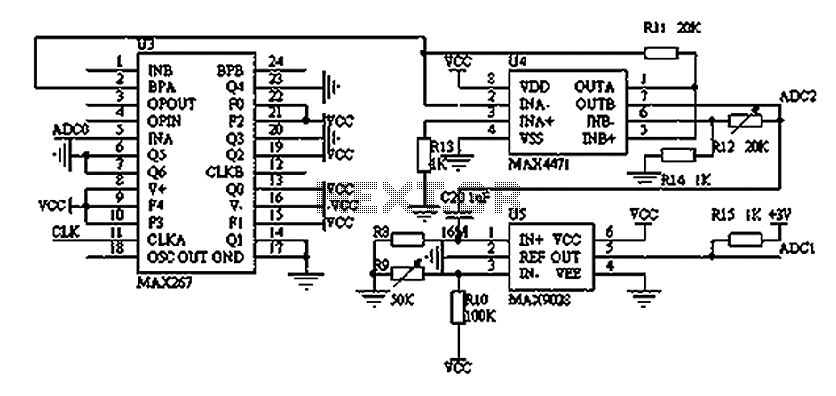
The filtering and amplifying circuit consists of two main components. The MAXIM MAX267 filter is an integrated circuit that can function as a low-pass, band-pass, high-pass filter, and other configurations, offering superior performance compared to traditional op-amp filters. The...
Thank you for your responses to my previous thread. I appreciate it. Please advise on how to convert a 24V DC and what circuit diagram should be used. To convert a 24V DC supply to a different voltage level, several...
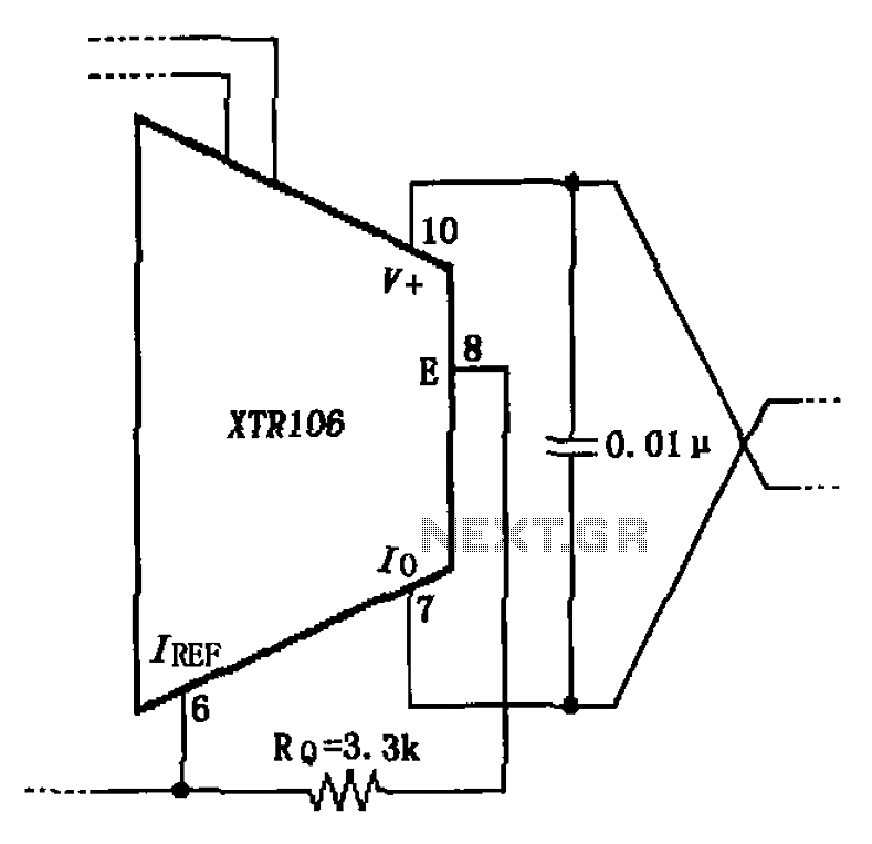
The circuit has been simplified due to the cancellation of an external transistor. The connection between the emitter terminals of the original external transistor and a 3.3k resistor will be removed, as this change has led to a decrease...