
19v dc regulation circuit diagram

To convert a 24V DC supply to a different voltage level, several circuit configurations can be employed depending on the desired output voltage and current requirements. A commonly used method for this purpose is the DC-DC buck converter, which steps down the voltage efficiently.
The basic structure of a buck converter includes an inductor, a switch (typically a MOSFET), a diode, and a capacitor. The operation begins when the switch is closed, allowing current to flow through the inductor, which stores energy in the form of a magnetic field. When the switch opens, the inductor releases its stored energy to the load through the diode, while the capacitor smooths the output voltage.
For a 24V DC input, the buck converter can be designed to output various lower voltage levels, such as 12V, 5V, or even lower, depending on the duty cycle of the switching signal. The duty cycle is the ratio of the time the switch is on to the total time period of the switching cycle and can be adjusted using a pulse-width modulation (PWM) signal.
The components required for this circuit include:
1. A suitable MOSFET rated for the input voltage and load current.
2. An inductor with an appropriate inductance value to handle the desired current without saturating.
3. A Schottky diode to ensure minimal forward voltage drop and fast switching.
4. Output and input capacitors to filter voltage spikes and smooth the output.
5. A control IC or PWM generator to manage the switching frequency and duty cycle.
The circuit should also include protection features such as overcurrent protection, thermal shutdown, and input/output voltage regulation to ensure reliable operation under varying load conditions.
In summary, a buck converter is an effective solution for converting a 24V DC input to a lower voltage, with the design tailored to specific application requirements. Proper component selection and circuit design are crucial for achieving high efficiency and stable performance.thanks for your replies in my previous thread posted, i really appreciate. pls., how do i, and what circuit diagram should i use to convert a 24v dc.. 🔗 External reference
Related Circuits
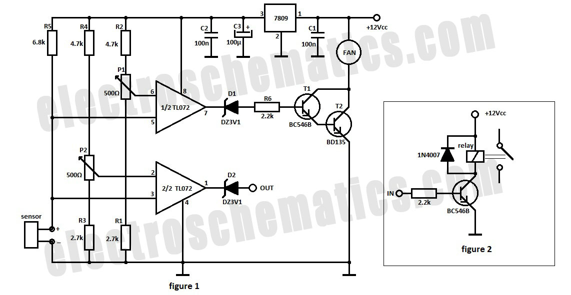
The automatic fan controller circuit depicted in the schematic features two comparators with distinct triggering points that can be adjusted independently. LM135 or... The automatic fan controller circuit is designed to regulate fan operation based on temperature variations. It employs...
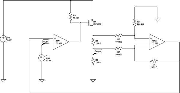
Create a 0-25 mA current limiter using a control voltage input of 0-5 V to regulate the current through a resistive load (R2), which can vary between 0-200 ohms. The O2 operational amplifier (op-amp) functions as a differential amplifier...
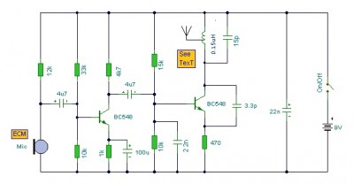
This is a mini FM transmitter circuit that utilizes two transistors. The audio sensitivity is notably high when paired with an ECM type microphone. The transmitter operates using a Hartley oscillator configuration. Typically, the capacitor in the tank circuit...
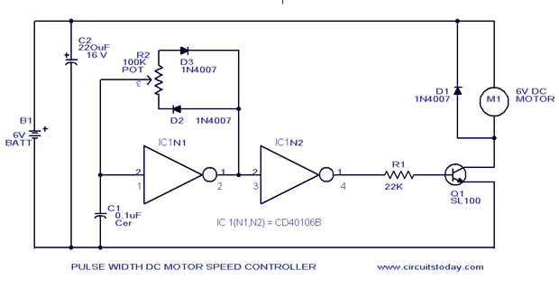
A simple PWM motor speed control circuit with a diagram and schematic for low power DC motors. This easy-to-make PWM DC motor controller is created using the IC CD40106B. The PWM (Pulse Width Modulation) motor speed control circuit utilizes the...
Mobile phone battery chargers available in local markets can be quite expensive. The circuit presented here offers a low-cost alternative for charging cellular phone batteries or battery packs with a rating of 7.2 volts. This low-cost phone battery charger circuit...
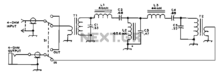
The circuit provides an 8-ohm output for connecting communication receivers and low-impedance speakers or headphones, featuring harmful interference suppression for continuous random voice transmission. The passband ranges from 55 to 2530 Hz with a 3 dB bandwidth. Inductors L1...