
The infrared sensor security device circuit

The circuit design integrates several functional modules to achieve its intended applications. The infrared sensor control circuit is responsible for detecting infrared signals, which can be utilized for motion detection or proximity sensing. This module typically includes an infrared emitter and a photodetector, which work together to sense the presence of objects within a designated range. When an object is detected, the output signal from the infrared sensor can trigger subsequent actions in the system.
The relay control circuit serves as an interface between the low-power infrared sensor output and higher power devices. This module typically includes a relay that can be activated by the output from the infrared sensor. When the sensor detects an object, it sends a signal to energize the relay, allowing it to close a circuit and power connected devices, such as alarms, lights, or other electrical appliances.
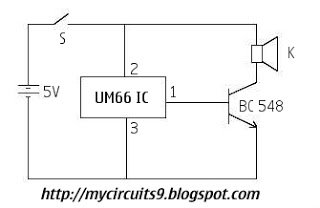
The music generating circuit is an additional feature that can be activated in response to the infrared sensor's output. This circuit may utilize a simple sound generator IC, such as the popular 555 timer, configured to produce specific tones or melodies. The music generation can serve as an alert or notification when the infrared sensor is triggered.
Overall, this circuit configuration is versatile and can be tailored for various applications, including security systems, automated lighting control, and interactive installations. The modular approach allows for easy integration of additional features or modifications based on specific requirements, making it suitable for both hobbyist projects and professional applications.See as the circuit, it consists of the infrared sensor control circuit, relay control circuit, music generating circuit and so on, which can be used in infrared alarm, timing control and other spots.. 🔗 External reference
Related Circuits

The PR4403 is an advanced version of the PR4402 40mA LED driver. It features an additional input known as LS, which can be activated by pulling it low to illuminate the LED. This functionality simplifies the construction of an...
This is a circuit diagram for a simple doorbell. The circuit can be assembled indoors, while the switch should be placed outside, making it easily noticeable for visitors. The operation of this circuit is similar to a previous project. The...

A color sensor is an engaging project for hobbyists. The circuit is capable of detecting eight colors, including blue, green, and red (the primary colors), as well as magenta and yellow. The color sensor circuit typically employs a photodiode or...
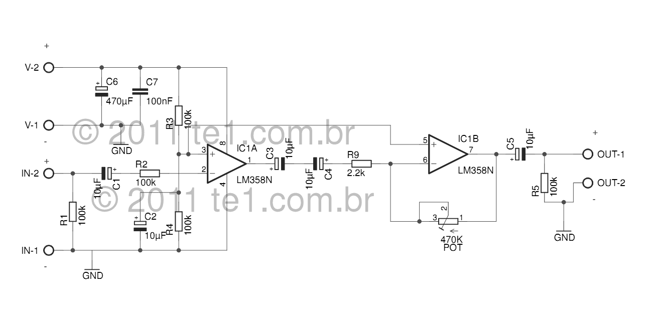
The LM358 series consists of two independent, high-gain, internally frequency-compensated operational amplifiers designed specifically to operate from a single power supply over a wide range of voltages. Operation from split power supplies is also possible, and the low power...

Deep discharge can damage a rechargeable battery. By disconnecting the battery from its load, this circuit halts battery discharge at a predetermined level of declining terminal voltage. Transistor Q1 acts as the switch. The overall circuit draws about 500µA...

The circuit functions as an AC blown fuse alarm. When the fuse (BX) is intact, 220 V AC voltage passes through a bridge rectifier composed of diodes VD1 to VD4. Resistor R1 limits the current, and the output is...