
The Itsy-Bitsy USB Lamp circuit

The Itsy Bitsy USB Lamp is a compact and efficient lighting solution that operates directly from a USB power source. The schematic design includes a USB Type-A connector, which provides a standardized connection to any compatible USB power supply. The cable length can be customized based on user requirements, allowing for flexibility in positioning the lamp.
At the core of the design is a high-efficiency white LED, selected for its brightness and low power consumption. The LED is connected in series with a resistor, which is crucial for limiting the current flowing through the LED to prevent damage. The value of this resistor is determined based on the forward voltage of the LED and the output voltage of the USB supply, typically 5V. The resistor's power rating must also be considered to ensure it can handle the power dissipation without overheating.
The in-line fuse holder serves a dual purpose: it provides a robust housing for the LED and resistor while also acting as a protective enclosure. This design choice enhances durability and safety, ensuring that the components are shielded from physical damage and environmental factors.
Overall, the Itsy Bitsy USB Lamp exemplifies an innovative approach to simple electronic design, combining practicality with ease of use. Its straightforward construction allows for easy assembly and modification, making it an excellent project for students and electronics enthusiasts alike.We`ve called it the Itsy Bitsy USB Lamp. It is such a delightfully simple idea we`re wondering why no-one ever thought of it before. It started life (and continues) as a student project at Massey University in Wellington, New Zealand - and in fact was submitted to us by the lecturer, Stan Swan. When we say simple, we mean it: just a USB plug on a suitable length of cable, a super bright white LED and a series resistor to limit LED current.
The LED and resistor are housed in an in-line fuse holder (without its innards!) which makes a superb little "wand" and also protects the electronics, such as they are.. 🔗 External reference
Related Circuits
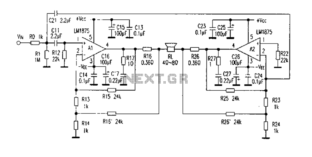
The DC current negative feedback BTL circuit illustrated in Figure 2 eliminates the standard BTL circuit capacitors C12 and C22, which affects the DC characteristics of the circuit. Resistors R16 and R26 function as sampling resistors, while R15, R16,...
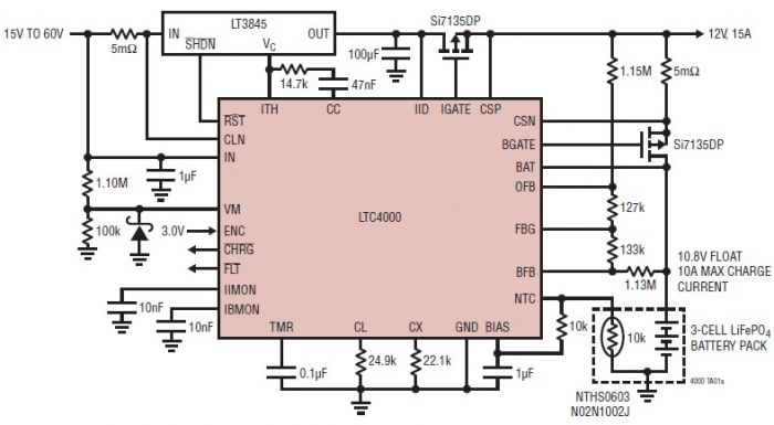
The LTC4000 high voltage controller, developed by Linear Technology, can be utilized to create a straightforward high current LiFePO4 battery charger. This charger delivers a fixed output voltage of 12 volts with a maximum output current of 15 A....
Operating radio transmitters without a license is illegal in most countries, so caution is advised with transmitter circuits. This FM low-power circuit is designed to operate within the 87-108 MHz band II, providing a range of approximately 20 to...

Binu submitted a new resource: Circuit and Program to Interface MT8870 with AT89S51 (version 1.0) - Decoding the DTMF signals from the telephone line. The circuit designed to interface the MT8870 DTMF decoder with the AT89S51 microcontroller is aimed at...
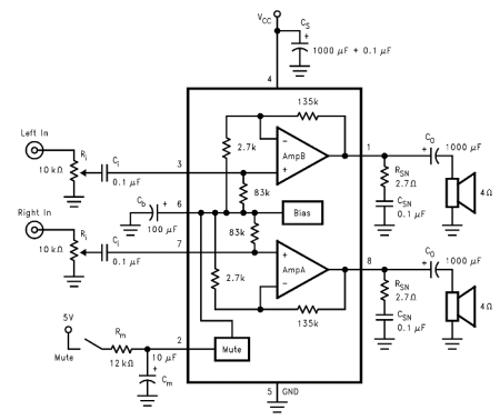
The internal mute circuit and pre-set gain resistors provide a cost-effective design solution. Output power specifications at both 20V and 24V supplies, along with a low external component count, offer significant value to consumer electronic manufacturers for stereo TV...
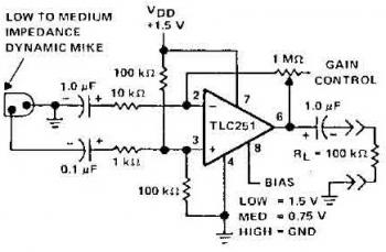
The schematic diagram of a microphone preamplifier is based on the operational amplifier TC251. The TC251 operates with low bias and functions with a supply voltage of only 1.5 V, drawing an electric current of just 10 mA, making...