
mic preamplifier circuit based tlc251

The microphone preamplifier circuit utilizing the TC251 operational amplifier is designed to enhance the signal from a microphone before it is processed by subsequent audio equipment. The TC251 is particularly advantageous in portable audio applications due to its low operating voltage and minimal current draw, which prolongs battery life.
The circuit's design includes a biasing network that ensures optimal performance across its specified frequency range, maintaining fidelity in sound reproduction. The frequency response of 27 Hz to 4.8 kHz is suitable for capturing the nuances of voice and instruments, making it effective for various audio applications, including recording and live sound reinforcement.
Incorporating a bias-select pin allows for flexibility in configuring the preamplifier to meet specific application requirements. By selecting different bias settings, the user can optimize the circuit for either lower power consumption or enhanced performance, depending on the needs of the application. This feature is particularly beneficial in scenarios where battery life is critical, allowing the designer to balance performance and efficiency.
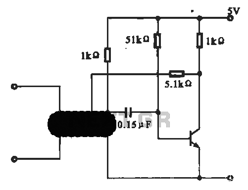
The TC251's stability at unity gain ensures reliable operation in feedback configurations, which is essential for maintaining signal integrity in audio processing. Overall, the microphone preamplifier circuit based on the TC251 operational amplifier represents a robust solution for low-power, high-performance audio applications.Here the schematic diagram of mic preamplifier which build based on operational amplifier TC251. The TLC251 is operating in low bias. The circuit works with only 1. 5 V supply draws electric current of only 10 mA, so the battery operation will be prefered. Circuit frequency response is 3dB, 27 Hz to 4. 8 kHz. The TLC251 are low-cost, low-power progr ammable operational amplifiers designed to operate with single or dual power supplies. Because the input common-mode range extends to the negative rail and the power consumption is very low, this chip is ideally suited for battery-powered or energy-conserving applications. A bias-select pin can be used to program one of three ac performance and power-dissipation levels to suit the application.
The series features operation down to a 1. 4V supply and is stable at unity gain. 🔗 External reference
Related Circuits
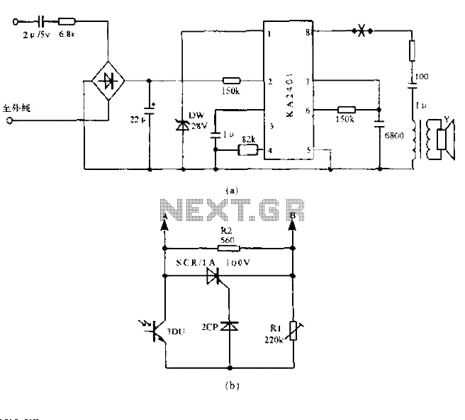
The circuit utilizes a standard telephone ringing circuit, KA2401, along with additional components to control lighting in response to a ringing signal. The light control circuit can be activated externally by AC when the ringing signal is received. The...
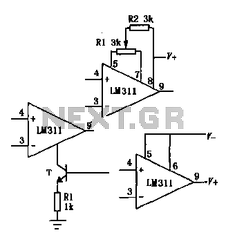
The LM111/211/311 power supply operates within a voltage range of 5V to 15V. It features bias current, offset current, and a differential input voltage range of 30V. The output is compatible with TTL, DTL, and MOS circuits, allowing it...
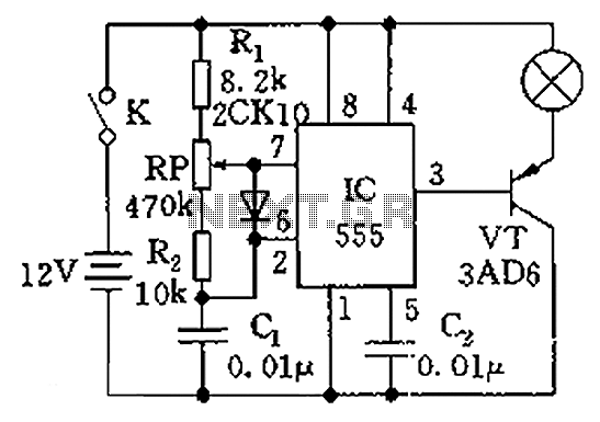
The circuit illustrated in the figure is a dimmer using the 555 timer as the core component. The 555 timer, along with resistors R1, RP, R2, and capacitor C1, forms an astable multivibrator. The oscillation frequency, f, is calculated...
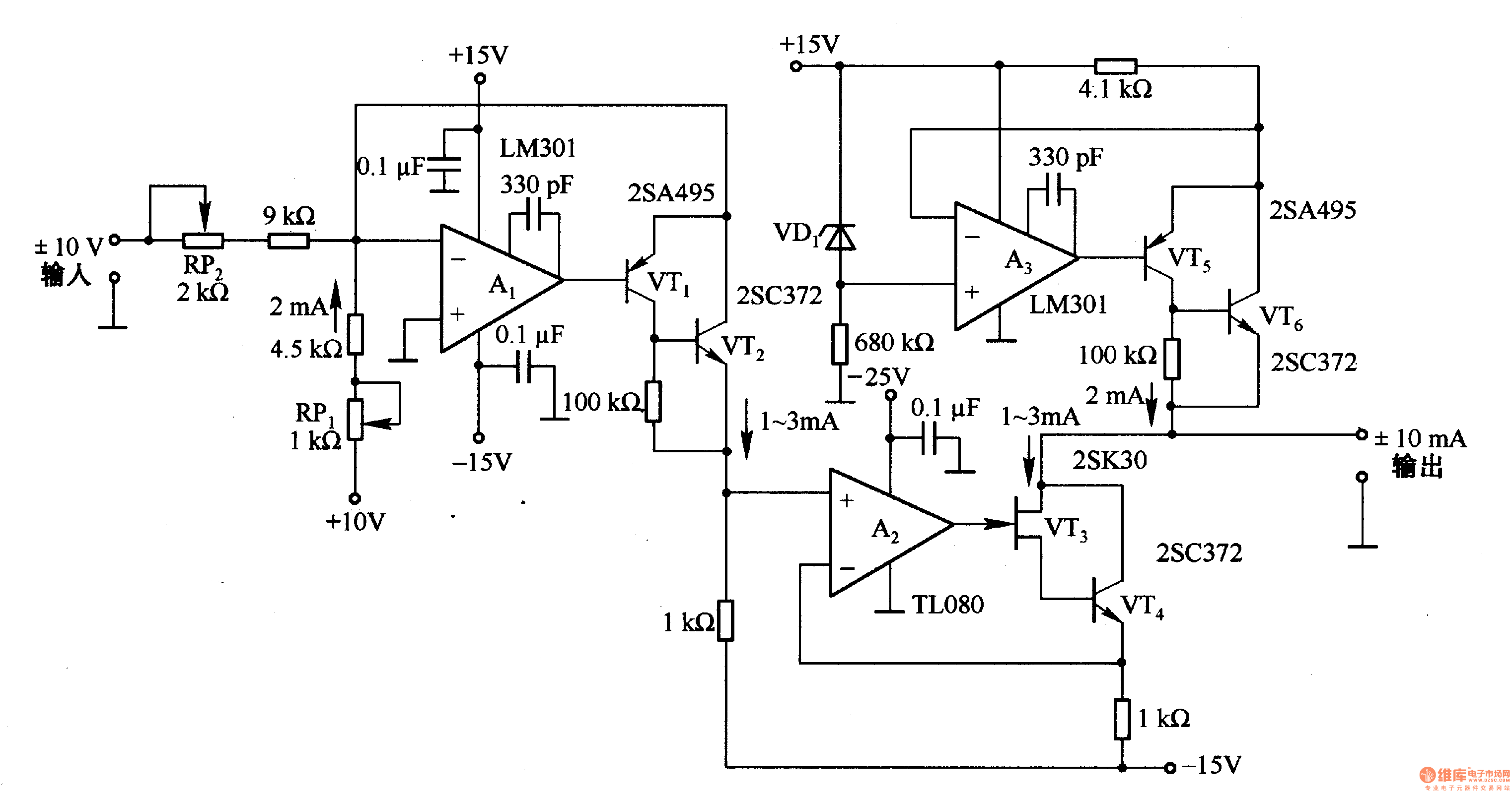
This circuit is designed for voltage-to-current conversion, specifically transforming a ±10V input voltage into a ±1mA output current. The conversion process is facilitated by operational amplifier A1 and transistors VT1 and VT2, which are responsible for altering the current...
This circuit illustrates an oscillator that is controlled by an optocoupler, utilizing photoelectric coupling to drive a transistor. The oscillator circuit described operates by employing an optocoupler to provide electrical isolation between its input and output stages while allowing control...
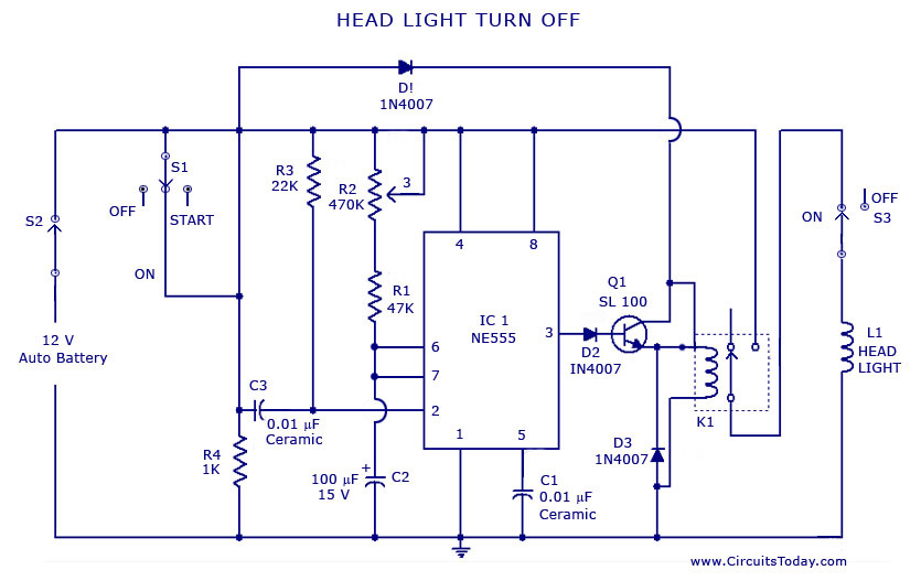
A circuit that can automatically turn off the headlights or lamps of a vehicle after a preset time. This light switching circuit is constructed using a 555 timer integrated circuit (IC). The described circuit utilizes the 555 timer IC in...