
The Multi-purpose signal generator circuit

The multi-purpose signal generator circuit employs integrated circuits (ICs) to achieve versatile frequency generation. The core of this circuit is based on oscillator configurations, which can produce square waveforms across a broad spectrum, from high frequencies suitable for RF applications down to sub-audio frequencies for various testing purposes.
The circuit typically utilizes a combination of astable and monostable multivibrator configurations to create stable oscillations. The astable multivibrator generates continuous square waves, while the monostable configuration can be triggered to produce single pulses of a defined duration. These oscillators can be implemented using common ICs such as the 555 timer or dedicated oscillator ICs.
Frequency dividers, such as the SN7490, are integral to this design. They reduce the output frequency from the oscillators to desired lower frequencies through a series of binary division stages. The SN7490 is a decade counter that can divide the input frequency by factors of ten, allowing for precise control over the output frequency range. This functionality is particularly useful in applications requiring specific frequency standards, such as VHF communication systems.
The feedback mechanism from the alternative oscillator to the frequency divider ensures that the oscillation frequency remains stable and accurate. By utilizing multiple divider stages, the circuit can produce a wide array of output frequencies, making it suitable for various testing and signal generation applications in electronic design and development.
Overall, this multi-purpose signal generator circuit is a valuable tool in electronics, providing flexibility for generating and manipulating signals across a wide frequency range.The multi-purpose signal generator circuit is composed of the integrated circuit oscillators and the frequency dividers, it produces the square wave from the high frequency to the sub-audio frequency, and it also produces the frequency standard VHF. The alternative oscillator part feeds the signal back to the 10-frequency divider stage. The extra SN7490 freq.. 🔗 External reference
Related Circuits

Feedback has indicated that the TDA6120Q test circuit, as shown in the figure, utilizes an input signal (Vi) composed of resistors Ra and capacitors C10 and C11, which are fed into the TDA6120Q at pins 2, 3, and 4....
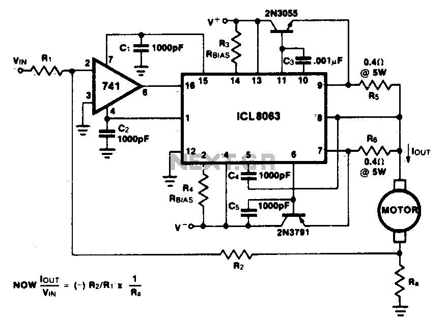
This minimum device circuit can be used to drive DC motors where there is some likelihood of stalling or lock-up. If the motor locks, the current drive remains constant, and the system does not destroy itself. This circuit is designed...

The circuit utilizes six 12-volt lead-acid batteries to power the load. Three batteries are connected in series to generate 36 volts, while the other three are connected in parallel to maintain 12 volts. The total discharge current is 30...

The 555 timer integrated circuit (IC) is an exceptionally versatile component utilized in various applications, including generating clock pulses, switch debouncing, and functioning as an output transducer. The standard 555 IC is packaged in an 8-pin configuration, available in...
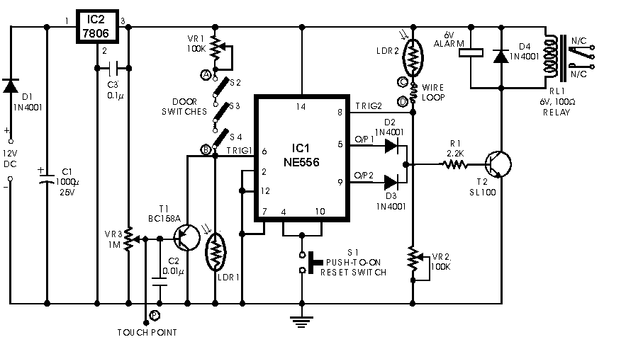
In this circuit, the alarm is activated under four different conditions: 1. When light falls on LDR1 (located at the entry to the premises). 2. When light falling on LDR2 is obstructed. 3. When door switches are opened or...
In night photography, long exposures are common, sometimes lasting several seconds to several minutes. HDR techniques often require taking a series of nine or more photos. Holding a remote trigger for an extended period can be tedious, leading to...