
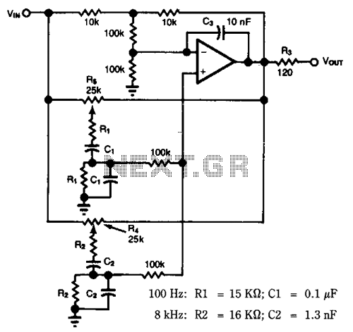
The same capacitance parameters 12dB-oct low-pass filter

This circuit design employs a passive vent filter configuration aimed at achieving specific frequency response characteristics. The Butterworth filter design is notable for its maximally flat frequency response, which is critical for applications requiring minimal phase distortion. The parameters defined in the circuit, such as A, port, and Q, are essential for determining the overall behavior of the filter. The relationship between R3 and the desired roar resistance is crucial for tuning the circuit to achieve optimal performance.
The choice of a Butterworth filter with a -12 dB/octave slope indicates a preference for a smooth roll-off, which is beneficial in applications where signal integrity is paramount. The operational amplifier's feedback capacitor plays a significant role in stabilizing the circuit and preventing unwanted oscillations. The specified cut-off frequency (fL) of 100 kHz is a critical design choice, as it defines the bandwidth of the filter. The adjustment of the input capacitance and parasitic capacitance is necessary to maintain the desired performance, particularly in high-frequency applications where such factors can significantly influence the circuit's behavior.
In summary, this circuit is designed to provide a stable and predictable frequency response, utilizing careful component selection and configuration to achieve the desired electrical characteristics while minimizing potential issues related to capacitance and feedback.In this circuit, A = 1, port = o.5, passive vent filter without distinction. When only care when dry l; Q = 1 / (3 - A), 12dB / oct filter of Butterworth King F0.707,4 mouth may be assumed as follows: a = 3 ^ ci / o) = 1.s8s, according to R4 = Rs (A-1), when R3 = iok0, the roar desirable 5.8sko, with s.iko and series from 7500. In this way may have a 4-1. 585 passband gain, and then connected to the front stage or satin circuit attenuates the feedback capacitor 111.
585. 0 mM role is to inhibit the OP amplifier input capacitance due to cl produced spikes. Although the cut-off frequency fL is set a certain degree of freedom, but when fL = Loo kHz, if the set. = iok Q, then Co F160pF, OP amplifier input capacitance 0- or parasitic capacitance will have an impact, so G.
From must reduce 5 ~ lOpF calculated values. In addition, OP amplifier gain can be replaced by a single wide band products.
Related Circuits
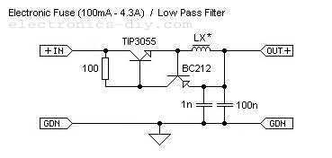
This is adjustable electronic fuse that can be used to protect power supplies from short circuits or can be also used to limit the current usage. It can be adjusted for currents from 100mA up to 4.3A. An adjustable electronic...
Most audio tone controls affect midband gain and often create booming or hissing sounds when activated. These problems can be avoided by using a dual Wien-bridge filter to provide independent control of the treble and bass frequencies. Experiments with...
Because it uses few parts, a printed circuit board is not necessary; components can simply be soldered to one another. However, a box is desirable for operating convenience. The case and aerial from a discarded toy walkie-talkie was used...
This circuit is a variable audio bandpass filter that features a low cutoff frequency adjustable from approximately 25 Hz to 700 Hz and a high cutoff frequency adjustable from 2.5 kHz to over 20 kHz. The roll-off rate is...
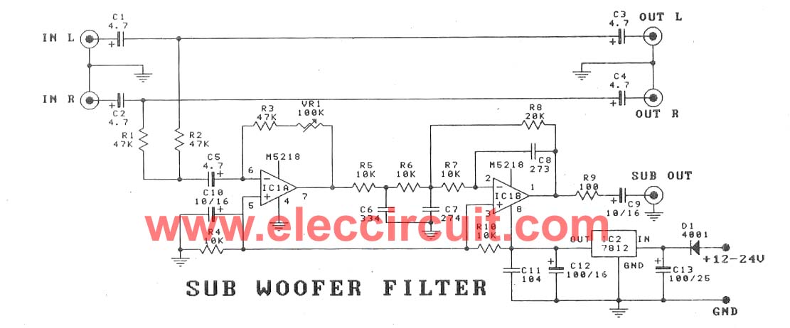
This subwoofer filter set is suitable for use with a high-quality car audio system. The circuit is designed to operate with a 12-volt DC power supply. The subwoofer filter set serves as an essential component in enhancing the audio experience...
What is the purpose of this circuit? Basically it has two roles: to pass the desired low frequency signals and stop the unwanted high frequency signals. Open the netlist file lpfilter1.cir with your SPICE simulator. Most simulators display the...