
RC Low-Pass passive Filter

The circuit described is a first-order low-pass filter, which serves to allow low-frequency signals to pass while attenuating high-frequency signals. The configuration consists of a resistor (R1) and a capacitor (C1) arranged in series. The output voltage (V(2)) is taken across the capacitor, while the input voltage (V(1)) is applied across the series combination of R1 and C1.
In this specific circuit, R1 is valued at 1 kΩ, and C1 is valued at 0.032 µF. The cut-off frequency (fc) can be calculated using the formula:
\[
f_c = \frac{1}{2\pi R C}
\]
Substituting the given values:
\[
f_c = \frac{1}{2\pi \times 1000 \, \Omega \times 0.032 \times 10^{-6} \, F} \approx 5 \, kHz
\]
This means that frequencies below 5 kHz will be allowed to pass with minimal attenuation, while frequencies above this threshold will be increasingly attenuated.
During the simulation, a sine wave generator is set to produce a 2 kHz signal, which falls below the cut-off frequency. As a result, this signal should appear at the output (V(2)), albeit with some minor amplitude reduction and a slight phase shift due to the reactive nature of the capacitor.
The transient analysis can be visualized in a SPICE simulator, where the input and output waveforms can be compared. Furthermore, an AC sweep analysis can be conducted to observe the filter's frequency response. This will provide a plot of the output magnitude (VM(2)) and phase (VP(2)) across a range of frequencies, illustrating how the filter attenuates signals above the cut-off frequency of 5 kHz. The expected behavior is that the output signal magnitude will remain relatively constant at low frequencies, while it will drop significantly as the frequency approaches and exceeds 5 kHz.What is the purpose of this circuit? Basically it has two roles: to pass the desired low frequency signals and stop the unwanted high frequency signals. Open the netlist file lpfilter1.cir” with your SPICE simulator. Most simulators display the netlist in a text editor window. You can view, modify and save the netlist from this window. Run a simulation. (TopSpice users click the traffic light on the toolbar; PSPICE users click the blue square.) View the transient (time) analysis at the input V(1) and output V(2).
For R1=1k, C1=0.032uF and sinewave generator at 2kHz, you should see the 2 kHz sinewave (desired signal) pass through to the output V(2) except for a slight decrease in signal and slight shift in time. As stated above, the circuit has two roles: to pass the desired low frequency signals and stop the unwanted high frequency signals.
But at what frequency does the filter change its behavior from passing the low ones to stopping the high ones. This is called the cut-off frequency. For R1=1k and C1=0.032uF you get fc = 5kHz. Run a simulation. Plot the AC (frequency) sweep results for the output magnitude VM(2) and phase VP(2). What does the magnitude look like before and after 5kHz? 🔗 External reference
Related Circuits
Many record players unfortunately exhibit two undesired side effects: rumble (noise caused by the motor and the turntable) and other low-frequency spurious signals. The active high-pass Chebyshev filter presented here was designed to suppress those noises. The filter has...
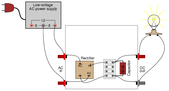
A bridge rectifier module is strongly recommended over building a bridge rectifier circuit using individual diodes. These modules are designed to be mounted on a metal heat sink. A metal enclosure is preferred over a plastic one due to...
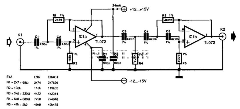
This is a subwoofer low-pass filter circuit, which is another variant based on the discharge from ST Microelectronics' TL062. The TL062 is a dual high-input impedance J-FET operational amplifier characterized by low power consumption and a high slew rate....
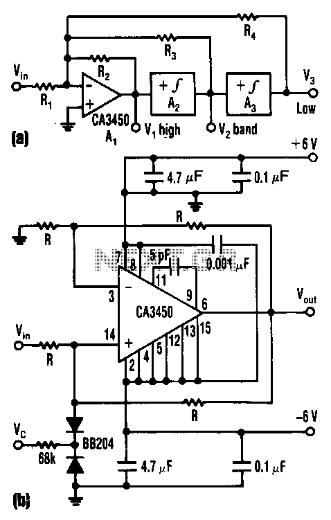
The control voltage Vc effectively adjusts the cutoff frequency w0 of this state-variable filter to any desired value, ranging from approximately 1.7 MHz to 5 MHz, using a BB 204 varicap and a resistance of 100 kΩ. Vc can...
The figures below illustrate using opamps as active 2nd order filters. Three 2nd order filters are shown, low pass, high pass, and bandpass. Each of these filters will attenuate frequencies outside their passband at a rate of 12dB per...
I designed this circuit for one friend of mine to be used as a small portable DJ mixer. The circuit is an audio mixer circuit so simple as it can be. There are two dual logarithmic potentiometers in the...