
The series connecting control circuit of electric contact pressure gauge and time relay

The circuit design features two time relays, KT1 and KT2, which play a crucial role in managing the operational timing of the electric contact pressure gauge (SP). The relays are strategically connected in series with the gauge to ensure that the system operates smoothly without the risk of electrical arcing or mechanical wear caused by premature contact.
When the system is activated, the time relays introduce a delay before the gauge contacts close, allowing sufficient time for the pressure to stabilize. This delay is essential to prevent the gauge from reacting to transient pressures that could occur during the motor's start-up or shutdown phases. The relays are selected based on their time delay characteristics to match the specific requirements of the application, ensuring that the pressure readings are accurate and reliable.
The relay contacts are designed to handle the electrical load of the motor control circuit, providing a safe interface between the pressure gauge and the motor's control system. The series connection ensures that both relays must be activated for the circuit to complete, adding an additional layer of safety and redundancy.
Furthermore, the circuit may include protective features such as fuses or circuit breakers to safeguard against overload conditions. Proper grounding and shielding techniques should also be implemented to minimize electromagnetic interference and enhance the overall reliability of the system.
Overall, the integration of time relays with an electric contact pressure gauge in this circuit design significantly improves the operational stability and safety of the motor control system, particularly in applications where pressure fluctuations are common.As shown in Figure, the circuit usestwo time relays KT1, KT2 to connect with thecontactsofelectric contact pressure gauge SP in series. When liquid or gas pressure has not yet reached, it can overcome thetrembling or spark phenomenons because of the SP`s incomplete separating andtoucing in the crash time of motor automatic start or stop,and itimprovesthe re..
🔗 External reference
Related Circuits
This circuit is intended for precision centigrade temperature measurement, with a transmitter section converting to frequency the sensor's output voltage, which is proportional to the measured temperature. The output frequency bursts are conveyed into the mains supply cables. The...
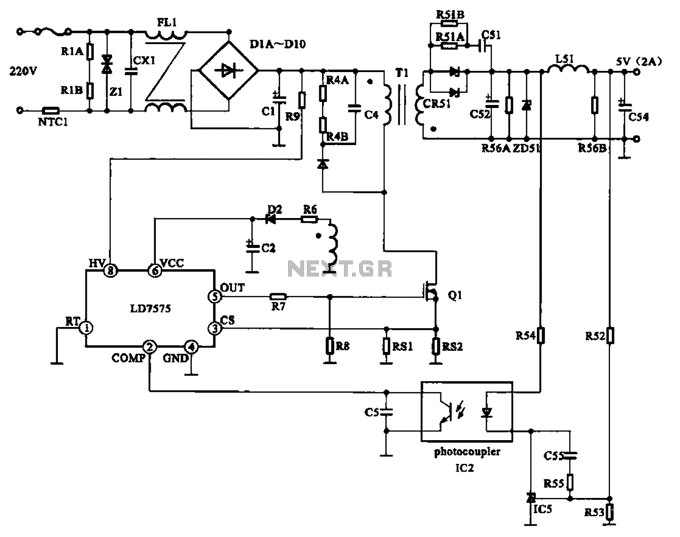
The AC adapter circuit is designed for portable digital products, converting low voltage DC into 220V AC. It features a circuit configuration for a switch power drill utilizing the oscillation IC LD7575 as a switch. This IC operates after...
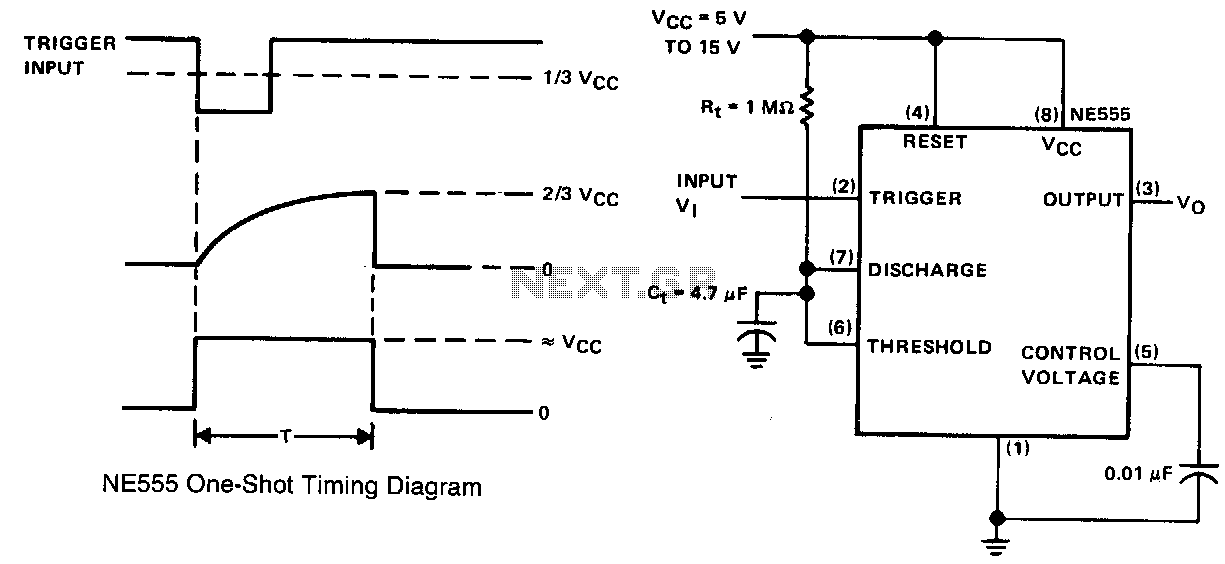
This simple circuit consists of only two timing components, Rr and Cr, the NE555 timer, and a bypass capacitor C2. Although C2 is not essential for operation, it is recommended for noise immunity. During standby, the trigger input terminal...
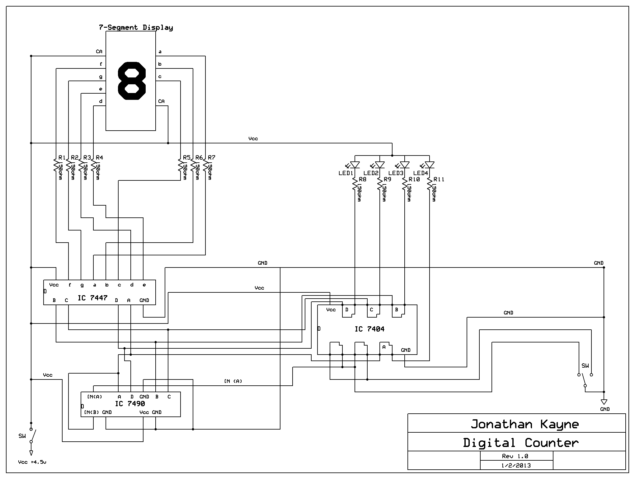
The Digital Counter Circuit is an electronic project that converts digital numbers (0-9) to binary (0-1). For those interested in understanding binary code, a PowerPoint presentation on the topic is available. Below are the parts list, schematic, and additional...
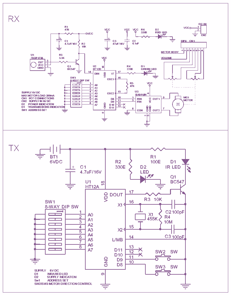
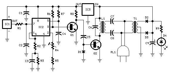
A nice circuit for using with audio preamplifiers, or any other circuit that use potentiometer and you need to control it from distance. The circuit includes Infrared transmitter and receiver with motor controller chip BA6418N. More: You can use...
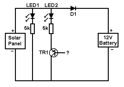
A small solar panel is used to maintain a 12V car battery. The panel provides approximately 75mA of current to the battery under full sunlight conditions. The described circuit employs a solar panel specifically designed for battery maintenance applications. The...