
Remote Thermometer circuit

The circuit comprises two main sections: the transmitter and the receiver. The transmitter section utilizes IC1, a precision centigrade temperature sensor, which provides an analog output voltage that is linearly proportional to the temperature. The output of IC1 is 10 mV per degree Celsius, which means at 20°C, the sensor outputs 200 mV.
This output voltage is fed into IC2, a voltage-to-frequency converter. This component is crucial as it transforms the analog voltage into a frequency signal. The conversion is designed such that an input voltage of 10 mV results in an output frequency of 100 Hz. Therefore, the output frequency can be calculated by multiplying the temperature in degrees Celsius by 10 Hz. For instance, at 25°C, the output frequency would be 250 Hz.
The frequency output from IC2 is then transmitted through the mains supply cables, utilizing the existing infrastructure for signal propagation. This method allows for a simple and effective means of transmitting the temperature measurement without the need for additional wiring.
In the receiver section, a frequency counter is employed to detect the frequency bursts transmitted through the mains. This section counts the frequency pulses and translates them into a readable format displayed on three 7-segment LED displays. The least significant digit is dedicated to representing tenths of a degree, allowing the circuit to display temperatures in the range of 00.0 to 99.9 °C.
The design of the circuit ensures that it is capable of providing precise temperature measurements with minimal interference, utilizing the mains supply for signal transmission and maintaining a user-friendly display for easy reading of temperature data.This circuit is intended for precision centigrade temperature measurement, with a transmitter section converting to frequency the sensor`s output voltage, which is proportional to the measured temperature. The output frequency bursts are conveyed into the mains supply cables. The receiver section counts the bursts coming from mains supply and shows the counting on three 7-segment LED displays.
The least significant digit displays tenths of degree and then a 00.0 to 99.9 °C range is obtained. IC1 is a precision centigrade temperature sensor with a linear output of 10mV/°C driving IC2, a voltage-frequency converter. At its output pin (3), an input of 10mV is converted to 100Hz frequency pulses. Thus, for example, a temperature of 20°C is 🔗 External reference
Related Circuits

This circuit comprises a 15V TOP224Y, 2A output DC switching power supply. It utilizes three integrated circuits: IC1 is a monolithic regulator (TOP224Y), IC2 is an optocoupler (NEC2501), and IC3 is a precision voltage reference (TL431). The TL431 (IC3)...

An LCD (liquid crystal display) is an electronically modulated optical device composed of multiple pixels filled with liquid crystals, arranged in front of a light source (backlight) or reflector to create images in color or monochrome. The block diagram...

This is a mini FM transmitter circuit that utilizes two transistors. The audio sensitivity is notably high when paired with an ECM type microphone. The transmitter operates using a Hartley oscillator configuration. Typically, the capacitor in the tank circuit...
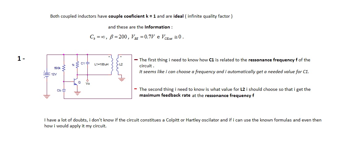
The first thing to understand is how capacitor C1 is related to the resonance frequency f of the circuit. It appears that selecting a frequency allows for the automatic determination of the necessary value for C1. There are uncertainties...

The electronic darkroom timer is constructed using a 555 oscillator/timer, a pair of general-purpose transistors, a buzzer, and an LED. The 555 timer (U1) is set up as an astable multivibrator, functioning as a free-running oscillator. The frequency of...
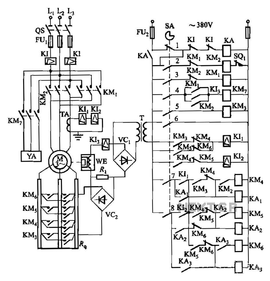
Attached to the wall is a high-rise building construction elevator, an essential piece of vertical transportation machinery. Its drive motor is typically a wound wire induction motor. The main switch and eddy current brake controls are also mounted on...