
The small resistance tester based on C8051F005 one-chip computer is designed

A comprehensive understanding of the circuit design and functionality of the survey meter can be derived from its operational principles and component selection. The tetrapolar measurement method is particularly advantageous as it mitigates errors caused by lead resistance and contact resistance, which are common in traditional measurement techniques. By using a known constant current source, the device ensures that the voltage drop across the resistance is accurately measured, facilitating reliable resistance readings.
The difference amplifier configuration is crucial in achieving high input impedance and minimizing the effects of common-mode signals. Operational amplifiers A1 and A2 are configured in a way that their common-mode voltages are equal, which helps in canceling out any noise and drift that might affect the measurement. The use of negative feedback in the amplifier circuit further enhances its stability and accuracy, allowing for precise amplification of the measured voltage drop.
The choice of high-accuracy, low-noise operational amplifiers and precision resistors is essential for maintaining the integrity of the measurements, especially when dealing with low resistance values. The design incorporates shielding techniques to prevent interference from external sources, ensuring that the readings remain accurate and reliable.
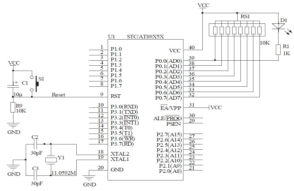
In conclusion, this survey meter represents a sophisticated integration of modern electronic components and design principles, resulting in a highly accurate and user-friendly device for resistance measurement. Its application in various fields, including laboratories and field research, underscores its versatility and effectiveness in providing precise electrical measurements.We have adopted the one-chip computer, utilize the advantage of the one-chip computer to design this survey meter. This survey meter can read out the resistance quantity measured from LCD display screen directly, the measurement limit is 10 2.
9999k, can store the data tested at the same time, then is sent into the upper computer by the serial port, pass the strong function of the upper computer, can analyze, deal with the data measured. The survey accuracy of this tester is up to 0. 1%, and adopt the tetrapolar measurement method, resistance quantity is not influenced by the lead wire size and contact resistance. Not only it is simple and convenient to measure, reading is ocular, and the survey accuracy, definition are also higher than the general electrical bridge.
It can be used for the laboratory, research institute, is especially suitable for the working site. It pursues local basic principles to be to adopt in examine at the resistance through the known constant current as above, take out the pressure drop on the resistance examined, amplify and change into 0- 3V direct-current volts by the amplifier, then send into the input terminus that C8051F005A/D changes, deal with the one-chip computer, pass the liquid crystal display direct display electric resistance value finally. Because of realizing the measurement of the minification resistance, require the definition of the amplifier to be high climax reach 10 V, The linear scale is good, input impedance is high, and demand to drift about low, noise suppression and antijamming capability are strong, we have designed the difference amplifier as signal processing circuit in Fig.
2 shows for this. This amplifier is made up of operational amplifier A1, A2 in fractional circuit of first difference, A3 makes up the fractional circuit of second difference, R3, R4, RW make up the FB network, has introduced the series negative feedback of the deep voltage, so there is higher input impedance, and A1, A2 all select as the input end with the phase terminal, then output voltage and drift voltage of their common mode are equal, pass the fractional circuit of A3 constituent difference again, can cancel each other, so it has very strong common mode inhibitory potencies and drift voltage of the minor output; A4 the intersection of voltage and reverse follower, function its grade is isolated enable. It is analyzed that this circuit can get the following equations. From 3 Know the type output voltage U4 is directly proportional to with the resistance RX examined. The multiple of the amplifier is made through R3, R4, RW, because the input voltage of the analog to digital converter is 0- 3V, the magnification that this instrument sets up the amplifier is 10 times, gets the direct-current volts of 0- 3V on U4 end.
In order to guarantee definition and stability of the amplifier, besides own advantage of the above-mentioned circuit, integrated operational amplifier A1, A2, A3 chooses high-accuracy, low-noise, low max495 that drifted about, the resistance of the feedback branch chooses the accurate resistance of the high-accuracy, low temperature coefficient, noise suppression that in addition has taken some shielding measures effectively and interfering with. Examined and adopted the tetrapolar i 🔗 External reference
Related Circuits
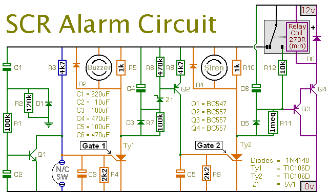
This is a simple SCR-based burglar alarm circuit. Its features include automatic exit and entry delays, along with a timed bell cut-off and reset. It is designed to be used with the usual types of normally-closed input devices such...
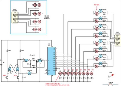
This circuit was developed to create a simple network tester that can be operated by a single individual. Commercial units typically require a second person to monitor the remote LEDs, as the transmitters lack the ability to continuously cycle...
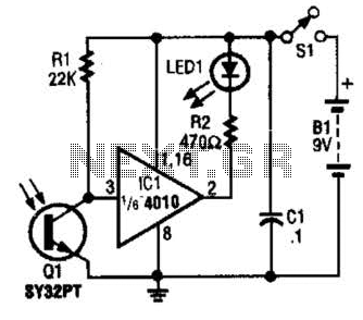
The IR Tester circuit indicates whether the button pressed on a remote control is functioning. Q1 is a phototransistor that is activated by infrared (IR) energy. The IR Tester circuit operates by detecting infrared signals emitted by remote control devices...
This circuit utilizes the widely available LM3914 integrated circuit (IC), which is straightforward to operate and does not require external voltage regulators due to its built-in voltage regulator. It can be powered from various sources. When the test button...
If you want to test an amplifier, a dummy load may be more convenient for speakers to use than actual speakers, due to noise or damage to the speakers. This circuit behaves in terms of impedance and frequency response...
This document will present an overview of two critical components within a one-chip computer: the timing/counter system and the interrupt system. Through this explanation, readers will gain insight into the operating principles of these systems. For illustration, consider an...