
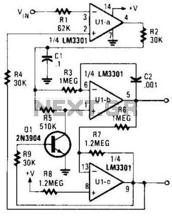
Remote-Control Tester Circuit

The IR Tester circuit operates by detecting infrared signals emitted by remote control devices when a button is pressed. The core component, Q1, is a phototransistor that responds to these IR signals by changing its conductivity. When IR light from the remote control reaches Q1, it generates a current flow through the phototransistor, which can be used to trigger an output indication, such as an LED or a buzzer.
In a typical configuration, the circuit may include a power supply, a resistor for current limiting, and an output device. The power supply can be a battery or any suitable DC source, providing the necessary voltage for the circuit operation. The resistor is connected in series with Q1 to ensure that the current flowing through the phototransistor remains within safe limits, preventing damage and ensuring reliable operation.
The output device, often an LED, is connected to indicate the presence of IR signals. When the remote control button is pressed, and the phototransistor is activated by the IR light, the LED will illuminate, providing a visual confirmation that the remote control is functioning correctly. In some designs, a buzzer may be used instead of an LED for audible feedback.
The circuit can be further enhanced by adding a variable resistor (potentiometer) to adjust the sensitivity of the phototransistor, allowing it to detect IR signals from various remote controls with different output power levels. Additionally, the circuit may include a small capacitor to filter any noise from the detected signal, ensuring that only valid IR signals trigger the output indication.
This simple yet effective design is useful for troubleshooting remote control devices and ensuring that they are operational, making it an essential tool for electronics enthusiasts and technicians. The IR Tester circuit lets you know if the button you press on a remote control is working. Ql is a photo transistor that is activated by IR energy.
Related Circuits
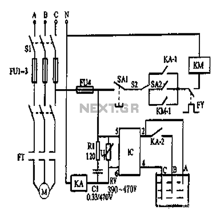
An automatic water tank system is illustrated in the circuit diagram. The circuit employs a PSSR AC solid-state relay, which is a new type of solid-state relay designed for AC applications. Unlike traditional solid-state relays (SSR), this PSSR not...
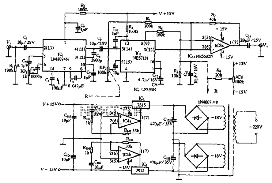
The NE571 and LM1894N form a dynamic expander circuit that enhances performance. This dynamic expander utilizes a variable bandpass filter with the LM1894N. It is particularly effective for dynamic expansion, requiring an RMS rectifier to mitigate noise modulation effects,...
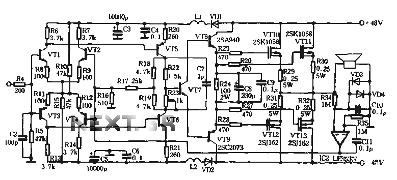
The self-designed amplifier circuit described is completely symmetrical and complementary, effectively utilizing the advantages of complementary NPN and PNP transistors to achieve a high degree of stability. The circuit features good symmetry in the push-pull amplification state, allowing for...
This circuit is straightforward. The initial 555 timer prevents the second timer from being activated while the first is operational. Drive the circuit with a simple 12-volt power supply. The circuit utilizes two 555 timer integrated circuits (ICs) configured in...
The Phase-Locked Loop (PLL) will synchronize with an input signal, providing both triangle and square wave outputs. A quad operational amplifier can be utilized in this circuit, making it suitable for audio and low-frequency radio applications. The Phase-Locked Loop (PLL)...
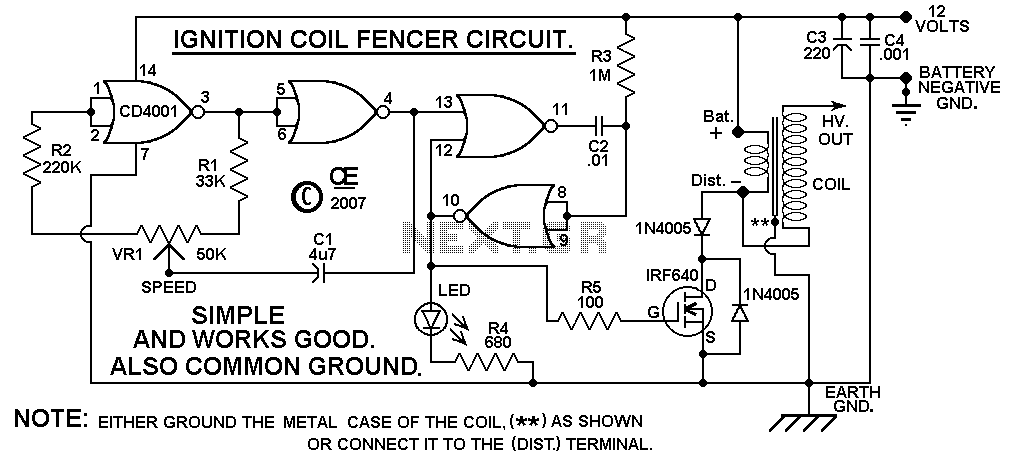
A circuit design based on a C-MOS chip to drive a car ignition coil. This is a very simple and efficient design for an electric fence. It puts out a very high voltage current pulse, yet it draws a...